29,99 €
Mehr erfahren.
- Herausgeber: Elektor International Media
- Kategorie: Wissenschaft und neue Technologien
- Sprache: Englisch
Ready to Master FPGA Programming? In this guide, we're diving into the world of Field-Programmable Gate Arrays (FPGAs)—a configurable integrated circuit that can be programmed after manufacturing. Imagine bringing your ideas to life, from simple projects to complete microcontroller systems! Meet the MAX1000: a compact and budget-friendly FPGA development board packed with features like memory, user LEDs, push-buttons, and flexible I/O ports. It's the ideal starting point for anyone wanting to learn about FPGAs and Hardware Description Languages (HDLs). In this book, you'll get hands-on with the VHDPlus programming language—a simpler version of VHDL. We'll work on practical projects using the MAX1000, helping you gain the skills and confidence to unleash your creativity. Get ready for an exciting journey! You'll explore a variety of projects that highlight the true power of FPGAs. Let's turn your ideas into reality and embark on your FPGA adventure—your journey starts now! Exciting Projects You'll Find in This Book > Arduino-Driven BCD to 7-Segment Display Decoder > Use an Arduino Uno R4 to supply BCD data to the decoder, counting from 0 to 9 with a one-second delay. > Multiplexed 4-Digit Event Counter > Create an event counter that displays the total count on a 4-digit display, incrementing with each button press. > PWM Waveform with Fixed Duty Cycle > Generate a PWM waveform at 1 kHz with a fixed duty cycle of 50%. > Ultrasonic Distance Measurement > Measure distances using an ultrasonic sensor, displaying the results on a 4-digit 7-segment LED. > Electronic Lock > Build a simple electronic lock using combinational logic gates with push buttons and an LED output. > Temperature Sensor > Monitor ambient temperature with a TMP36 sensor and display the readings on a 7-segment LED.
Das E-Book können Sie in Legimi-Apps oder einer beliebigen App lesen, die das folgende Format unterstützen:
Seitenzahl: 163
Veröffentlichungsjahr: 2024
Ähnliche

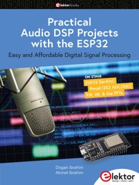

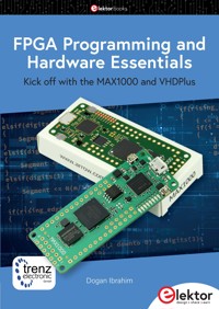
FPGA Programming and Hardware Essentials
Kick off with the MAX1000 and VHDPlus
●
Dogan Ibrahim
●This is an Elektor Publication. Elektor is the media brand of Elektor International Media B.V.PO Box 11, NL-6114-ZG Susteren, The NetherlandsPhone: +31 46 4389444
●All rights reserved. No part of this book may be reproduced in any material form, including photocopying, or storing in any medium by electronic means and whether or not transiently or incidentally to some other use of this publication, without the written permission of the copyright holder except in accordance with the provisions of the Copyright Designs and Patents Act 1988 or under the terms of a licence issued by the Copyright Licencing Agency Ltd., 90 Tottenham Court Road, London, England W1P 9HE. Applications for the copyright holder's permission to reproduce any part of the publication should be addressed to the publishers.
●Declaration
The author and publisher have made every effort to ensure the accuracy of the information contained in this book. They do not assume, or hereby disclaim, any liability to any party for any loss or damage caused by errors or omissions in this book, whether such errors or omissions result from negligence, accident, or any other cause.
The author expresses his sincere gratitude to Arrow Electronics and Trenz Electronic for granting permission to include various tables, figures, and program codes in this book.
●ISBN 978-3-89576-644-2 PrintISBN 978-3-89576-645-9 eBook
●© Copyright 2024 Elektor International Mediawww.elektor.comEditor: Glaucileine VieiraPrepress Production: D-Vision, Julian van den BergPrinters: Ipskamp, Enschede, The Netherlands
Elektor is the world's leading source of essential technical information and electronics products for pro engineers, electronics designers, and the companies seeking to engage them. Each day, our international team develops and delivers high-quality content - via a variety of media channels (including magazines, video, digital media, and social media) in several languages - relating to electronics design and DIY electronics. www.elektormagazine.com
Contents
Preface
Chapter 1 • Introduction
1.1 What is a Field Programmable Gate Array (FPGA)?
1.2 Some popular FPGA development boards
Chapter 2 • The MAX1000 FPGA Hardware
2.1 Overview
2.2 The MAX1000 Hardware
2.2.1 Board Indicator LEDs
2.2.2 Block Diagram
2.2.3 Clock Circuitry
2.2.4 User LEDs
2.2.5 Push Buttons
2.2.6 Accelerometer
2.2.7 Arduino Connectors
2.2.8 Pmod Connector
2.2.9 UART Communication
2.2.10 Power supply circuitry
Chapter 3 • Software Installation – VHDPlus IDE
3.1 Overview
3.2 Installing the VHDPlus IDE
3.3 Your first program
3.3.1 Downloading the compiled code to your FPGA
3.3.2 Installing packages and library files to VHDPlus
3.3.3 Simulating the program
Chapter 4 • The VHDPlus Language
4.1 Overview
4.2 Data types and operators
4.2.1 Data types
4.2.2 Operators
4.3 Binary logical operators
4.3.1 Relational operators
4.3.2 Arithmetic operators
4.3.3 Concatenation operator
4.3.4 Shift operators
4.3.5 Type conversion
4.4 Declarations, assignments, and constants
4.4.1 Declarations
4.4.2 Assignments
4.4.3 Constants
4.5 VHDPlus program flow statements
4.5.1 If..Else..Elsif
4.5.2 Case and When
4.5.3 For
4.5.4 While
4.5.5 Wait
4.5.6 Step
4.6 VHDPlus program template
4.6.1Main
4.6.2 Process
4.6.3 Thread
4.6.4 Function
Chapter 5 • Example VHDPlus Projects
5.1 Overview
5.2 Project 1 – Flashing LED
5.3 Project 2 – Two alternately flashing LEDs
5.4 Project 3 – Using an external LED
5.5 Project 4 – Chasing LEDs
5.6 Project 5 – Binary counter with LEDs
5.7 Project 6 - LED with button control
5.8 Project 7 - LED with External Button Control
5.9 Project 8 – Event counter
5.10 Project 9 – Full adder
5.11 Project 10 – Multiplexer
5.12 Project 11 – BCD to seven-segment display decoder
5.12.1 Connecting a 7-segment display to the FPGA
5.13 Project 12 – BCD to seven-segment display decoder counter with Arduino Uno R4
5.14 Project 13 – 4-bit counter
5.15 Project 14 – 8-bit serial-in parallel-out shift register
5.16 Project 15 – Edge triggered D-type flip-flop
5.17 Project 16 – Demultiplexer
5.18 Project 17 – Multiplexed 4-digit 7-segment LED
5.19 Project 18 – Multiplexed 4-digit 7-segment LED event counter
5.20 Project 19 – Multiplexed 4-digit 7-segment LED seconds counter
5.21 Project 20 – Switch contact debouncing
Chapter 6 • Analog-to-Digital Converter (ADC)
6.1 Overview
6.2 MAX1000 analog inputs
6.3 Project 1 – Voltmeter
6.3.1 Extending the input range
6.4 Project 2 – Temperature sensor
6.5 Project 3 – Light dependent resistor (LDR)
Chapter 7 • Serial Communication
7.1 Overview
7.2 MAX1000 FPGA serial port
7.3 Project 1 – Controlling the on-board LEDs with serial communication
Chapter 8 • Pulse Width Modulation (PWM)
8.1 Overview
8.2 Basic theory of the pulse width modulation
8.3 Project 1 – PWM waveform with a fixed-duty cycle
8.4 Project 2 – Mosquito repeller
8.5 Project 3 – Variable duty cycle – Dimming an LED
Chapter 9 • Ultrasonic Sensor
9.1 Overview
9.2 Project 1 – Ultrasonic distance measurement
Chapter 10 • The I2C Bus
10.1 Overview
10.2 The I2C bus
10.3 The I3C bus
10.4 Differences between the I2C and I3C
10.5 Project 1 – Port expander using the I2C bus on MAX1000 FPGA
Chapter 11 • The SPI Bus
11.1 Overview
11.2 Project 1 – SPI Port expander
Chapter 12 • Using LCD
12.1 Overview
12.2 HD44780 LCD module
12.3 Project 1 – Displaying text on LCD
Chapter 13 • Programming in VHDL
13.1 Overview
13.2 Project 1 – Flashing LED
13.3 Project 2 – Button and LED
13.4 VHDPlus to VHDL conversion
Chapter 14 • MAX1000 FPGA Python Programming
14.1 Overview
14.2 Python programming
Chapter 15 • NIOS II
15.1 Overview
15.2 Creating a NIOS II processor
15.3 Project 1 – Displaying a message using the NIOS II processor as Arduino
15.4 Project 2 – Alternately flashing two LEDs
Chapter 16 • Accelerometer Project
16.1 Overview
16.2 The project
16.2.1 Testing the program
Chapter 17 • Other Projects Provided With the VHDPlus IDE
Chapter 18 • Quartus Prime Lite Schematic Design
18.1 Overview
18.2 Project 1 – D-type flip-flop with LED output
18.3 Project 2 – Electronic lock
18.3.1 The truth table
Appendix • Bibliography
Preface
Almost all complex digital systems are nowadays designed using hardware description languages (HDL). Designs involve using computationally intensive hardware such as ASICs, FPGAs, and PLDs. This is a significant change from earlier designs, which relied on using small and medium-scale integrated circuits.
An FPGA is a configurable integrated circuit that can be programmed after manufacturing. They consist of an array of programmable logic blocks with connecting grids that can be configured and programmed for the design of a complex digital circuit. FPGAs are nowadays used in the automotive industry, aerospace, telecommunications, digital signal processing, and in many industrial sectors. FPGAs can be configured to perform complex combinational logic functions as well as sequential digital logic operations. For example, it is possible to design a complete microcontroller system using FPGAs with a suitable HDL.
MAX1000 is a small, inexpensive, but rather powerful FPGA development board. It consists of memory, user LEDs, push-buttons, input-output ports, and several other on-board interface devices. MAX1000 is highly suitable for starters who want to learn about FPGAs, and also who want to learn to use HDLs. Users can design complex digital circuits and then implement them on the MAX1000 FPGA using its LEDs, I/O, interface features such as SPI, UART, I2C, I2S, etc. Perhaps the biggest advantage of MAX1000 is its simplicity and low cost compared to other FPGAs.
There are several HDLs in use today, such as VHDL, and Verilog. The design is either at an abstract behavioral level or at the structural level where more detailed gate-level designs are done. The MAX1000 can be programmed using the VHDL, VHDPlus, or Python programming languages.
In this book, you will learn to use the VHDPlus FPGA programming language to program the MAX1000. VHDPlus is a superset of the popular programming language VHDL. Users who are familiar with VHDL should find it easier to learn to use VHDPlus. VHDPlus runs on a PC and includes a large number of libraries and examples. Users can develop their FPGA projects on the PC using the VHDPlus IDE and then download the code to the MAX1000. In addition to a rich instruction set, VHDPlus also includes a simulator that helps users simulate their designs before downloading to the MAX1000. Another important feature of VHDPlus is that it supports NIOS II processor creation, where the Arduino Uno processor can be created and programmed inside the MAX1000 FPGA.
Many working and tested projects are given in the book using the VHDPlus programming language and implemented on the MAX1000 FPGA hardware. Readers can easily modify these programs for their own designs.
I hope you enjoy reading the book and that you use the MAX1000 FPGA together with VHDPlus in your next digital design.
Dr. Dogan Ibrahim
London, 2024
Chapter 1 • Introduction
1.1 What is a Field Programmable Gate Array (FPGA)?
Field Programmable Gate Arrays (FPGAs) are semiconductor devices that are designed around a matrix of configurable logic blocks (CLBs) connected via user-programmable interconnections. Although CLB is the fundamental logic module of an FPGA, other modules such as interconnects, input-output blocks, and Digital-Signal-Processing (DSP) blocks are other modules within an FPGA.
The FPGA market has been growing steadily in the last decade and it is expected to grow to over USD 20 billion by the year 2030. The market is dominated by famous manufacturers such as Intel/Altera, Lattice, AMD/Xilinx, Microchip, Flex Logix, QuickLogic, Renesas, and some smaller companies that offer lower-cost products. Currently, Xilinx and Altera lead the FPGA market, with Microchip growing in the market.
FPGAs can be programmed by users to desired functionalities or applications after they are manufactured. Application Specific Integrated Circuits (ASICs) are similar to FPGAs, but ASICs are custom manufactured for specific applications or functionalities. Another difference between FPGAs and ASICs is that FPGAs are designed for lower speed and lower complexity. Complex Programmable Logic Devices (CPLDs) are also used in applications similar to FPGAs and ASICs, but they are less flexible and less customizable, although offer higher speeds than FPGAs at lower costs. CPLDs are usually used in less complex front-end logic applications, such as in interfacing, control, and state machines.
FPGAs find applications in various electronic fields, such as in digital signal processing, automotive industries, aerospace & defense electronics, consumer electronics, data centers, industrial applications, high-performance computing, medical applications, image and video processing, security, all fields of electronic communication, complex digital system design, and many more.
The logic blocks of an FPGA can be programmed to perform complex combinational or sequential logic functions. Input/output pads, reprogrammable interconnect, and programmable logic blocks make up a field-programmable gate array. Flip-flops or memory blocks may be utilized as memory components in the logic blocks of a field-programmable gate array. The logic blocks can carry out simple to complicated computational operations.
FPGAs are normally programmed using high-level description languages (HDL) such as VHDL, Verilog, VHDPlus, Python, C, C++, or several others.
The first FPGA was developed by Altera in 1984 (the EP300). This was in the form of an EPROM memory which had a quartz window so that the contents of the memory could be erased using an ultra-violet lamp. The first commercial FPGA was produced by Xilinx in 1985 (the XC2064). This chip had programmable gates and programmable interconnects between these gates.
The real FPGA manufacturing started growing in the 1990s. By the year 2013, Altera had 31% of the market share, Actel had 10%, and Xilinx had 36%. Together these three companies represented 77% of the FPGA market.
There are basically three types of FPGAs: static random-access memory (SRAM)-based, flash-based, and anti-fuse. SRAM-based FPGAs use volatile SRAM cells to store configuration data, which must be loaded every time an FPGA powers up. They are commonly used for prototyping, development, and applications where frequent design changes and tests are needed. Flash-based FPGAs use non-volatile flash memory cells to store configuration data, allowing the FPGA to retain its configuration at power-up. Flash-based FPGAs are most suitable for applications that need instant-on functionality without needing to reload the configuration data at each power cycle. Anti-fuse FPGAs are non-volatile and retain their data at power-up but are one-time programmable and cannot be undone or reconfigured by users. These limitations make anti-fuse FPGAs ideal for applications that require security and do not need additional reprogramming, such as in defense, aerospace, or other high-reliability applications.
The steps to program an FPGA are:
Use a high-level description language (e.g., VHDL) to describe the required functionality of the task as a codeSimulate (if possible) and verify the codeConfigure the FPGA device and load the code onto the deviceRun your code on the FPGATest your code in real-time1.2 Some popular FPGA development boards
There are many FPGA development boards available from companies such as Arrow Electronics, Trenz Electronic, AMD Xilinx, Lattice Semiconductor, QuickLogic, Altera Corporation, Microchip Technology, Terasic, Microsemi, Efinix, Digilent, GOWIN Semiconductor, Invent Logic, etc. The basic specifications of some popular FPGAs are given in this section.
Artix-7 FPGA AC701
This FPGA board (Figure 1.1) is manufactured by AMD. It is a high performance, high functionality FPGA, costing around $1,500. The Artix-7 is used by some other manufacturers as well. Some of its features are:
215,360 logic cells740 DSP slices13,140 memory cells16 GTP transceivers500 I/O pinsSome of its board features are:
5 x user push buttons4 x user LEDs4-position user DIP switches2 x 16 LCD displayHDMI video outputSD card slot10/100/1000 Mbps EthernetUART to USB bridgeJTAG headerPmod headerFurther details on Artix-7 are available from the Xilinx website:
https://www.xilinx.com/products/boards-and-kits/ek-a7-ac701-g.html
Figure 1.1 Artix-7 development board
Spartan-7 SP701 FPGA
This board (Figure 1.2) is manufactured by AMD. It is a high-performance FPGA, costing around $800. Some of its features are:
102,400 logic cells1,100 kB DRAM, 4,320 KB16 Block RAM160 DSP slices400 I/O pins1 x analog-to-digital converter8 x clock management tiles1 x configuration AESSome of its board features are:
6 x Pmod headers6 x user push buttonsHDMI interface2 x Ethernet portsMIPI camera interfaceMIPI display connectorJTAG connectorFigure 1.2 Spartan-7 development board
Arty A7-100T
This FPGA development board (Figure 1.3) from Digilent costs around $299. Its basic features are:
101,440 logic cells240 DSP slices4,860 Kbits memoryAnalog-to-digital converterSome of its board features are:
10/100 Mbps Ethernet portUSB-UART bridge4 x switches4 x buttons4 x LEDs4 x RGB LEDs4 x Pmod connectorsArduino shield connectorsFurther information on Arty A7-100T is available at the following link:
https://digilent.com/shop/arty-a7-100t-artix-7-fpga-development-board/
Figure 1.3 Arty A7-100T development board
USB104 A7
This FPGA (Figure 1.4) from Digilent is based on ADM Xilinx Artix-7, costing $349. Its basic features are:
101,440 logic cells240 DSP slices4,860 Kbits memorySome of its board features are:
4 x LEDs2 x push buttonsUSB-UART bridge3 x Pmod portsUSB-JTAG programming1 x standard SYZYGY portFurther information on Arty A7-100T is available at the following link:
https://digilent.com/shop/usb104-a7-artix-7-fpga-development-board-with-syzygy-compatible-expansion/
Figure 1.4 USB104 A7 development board
BeMicro MAX10
This FPGA development board (Figure 1.5) from Arrow Electronics is designed to get you started using an FPGA. Its basic features are:
8,000 logic elements414 Kbits of memory2 x PLLs24 x 18x18 multipliersAnalog-to-digital converter, 17 analog inputs250 I/OSome of its board features are:
ADXL362 three-axis accelerometerAD5681 12-bit DACtemperature sensorthermal resistorphoto resistorFurther information on BeMicro MAX10 is available at the following link:
https://www.arrow.com/en/products/bemicromax10/arrow-development-tools
Figure 1.5 BeMicro MAX10 development board
MAX1000 FPGA
This is the FPGA used in this book (Figure 1.6). It is from Arrow Electronics and is designed to get you started using an FPGA, costing as low as $30. Although the board is described in later chapters in detail, its basic features are:
Number of logic elements depends on the model and varies from 2,000 to 16,000User flash depends on the model and varies from 96Kb to 2,368Kb8 MB SDRAM12 MHz oscillator, PLL to 100 MHzAnalog-to-digital converterUSB-BridgeSome of its board features are:
8 x user LEDs2 x user buttonsMotion sensor3-axis AccelerometerPmod header holesArduino headerJTAG headerUser I/O headerFurther information on MAX1000 is available at the following link:
https://www.arrow.com/en/products/max1000/arrow-development-tools
Figure 1.6 MAX1000 development board
Daventech iceWerx iCE40-HX8K FPGA
This is a low-cost FPGA board (Figure 1.7) from iceWerx, costing around £30. Its basic specifications are:
4 x 10-bit analog channels12 MHz clock7680 logic cells128 kbits embedded RAM (32 × 4 kbit blocks)2 PLL'sFigure 1.7 iCE40-HX8K development board
Sparkle FPGA PYNQ-Z2
This FPGA development board costs around £130 (Figure 1.8). Its basic features are:
1.3 M reconfigurable gates650 MHz Cortex-A9 processor512 MB DDR3/128 Mbit flashMultiple ports with USB, Ethernet, audio and video2 Pmod portsArduino shield connectorRaspberry Pi connectorFigure 1.8 Sparkle PYNQ-Z2
Basys 3 Artix-7 FPGA Trainer Board
This FPGA board costs around £150 (Figure 1.9) and it is recommended for starters. The basic features of this board are:
16 MB memory1,800 Kbits fast block RAMInternal clock speed over 450 MHzOn-chip analog to digital converterUSB-UART bridgeVGA output4-digit 7-segment display16 user switches16 user LEDs5 user pushbuttons4 Pmod portsUSB-JTAG port for FPGA programming and communicationPower switchExternal power connectorReset buttonFigure 1.9 Basys 3 Artix-7 FPGA
CYC1000 FPGA
This is a small but powerful FPGA integrating an Intel Cyclone 10 LP FPGA (Figure 1.10), costing around £30. The basic features are:
Intel Cyclone 10 LP FPGA:25 kLE, 66 Memory blocks (9K), 594 Memory blocks (Kb), 18 x 18 multipliers -> 668 MByte SDRAM8 MByte Flash (W25Q64JVSSIQ)ST Microelectronics LIS3DH 3-axis accelerometer21 I/O Arduino MKR compatible headersJTAG and UART via Micro USB2 connector2 x 14 pin headers (2.54 mm pitch) for 23 GPIOs1 x 3 pin header for 2 GPIOsPmod: 2x6 Pin support8 x configurable LEDs1 x user push button5.0 V single power supply with on-board voltage regulatorssize: 6.15 x 2.5 cmFigure 1.10 CYC1000 FPGA
Chapter 2 • The MAX1000 FPGA Hardware
2.1 Overview
The MAX1000 (Figure 2.1) is a customizable development board, built around the MAX10 FPGA, which is the industry's first single-chip programmable and non-volatile logic device. MAX1000 is equipped with an Arrow USB Programmer 2, SDRAM, flash memory, accelerometer sensor, PMOd, and ARDUINO connectors, making it an ideal product for beginners as well as for project developers.
In this chapter, we will look at the hardware details of the MAX1000 development board.
Figure 2.1 The MAX1000 FPGA
2.2 The MAX1000 Hardware
Figure 2.2 shows the MAX1000 board layout where the locations of various components and connectors are shown. Next to the Pmod connector holes is the SDRAM with the accelerometer sensor located at its top right corner. The MAX10 chip is on the right of the SDRAM. The flash memory and the oscillator are located next to the MAX10 chip. On the right-hand side of the board, you can see the USB Bridge and the mini USB connector which is used to power the board. The user I/O pins are at the top of the board, the user buttons are at the top right, and the user LEDs are located at the bottom right part of the board. The recommended maximum logic level HIGH voltage is +3.3 V. Voltage level converters must be used if a +5 V source is to be interfaced to MAX1000 pins.
Figure 2.2 MAX1000 board layout (Arrow MAX1000 User Guide)
In summary, the following are available on the board:
Intel MAX10 deviceArrow USB Programmer 264Mbit SDRAM64Mbit flash memory1 x 12 MHz MEMS oscillator1 x optional MEMS oscillator of preferred frequency8 x red user LEDs2 x board indicator LEDs2 x user buttons1 x 3-axis accelerometer1 x 12-pin Pmod header (just the holes)1 x user JTAG header (just the holes)1 x user I/O header (just the holes)Mini USB type-B connector2.2.1 Board Indicator LEDs
The upper board indicator LED (D1) is ON when +3.3 V power is applied to the board. The lower board indicator LED (D10) is ON when configuration data is loaded into MAX1000 without error (Figure 2.3).
Figure 2.3 Board indicator LEDs (Arrow MAX1000 User Guide)
2.2.2 Block Diagram
The block diagram of the board is shown in Figure 2.4. The design is centered around the MAX10 chip.
Figure 2.4 MAX1000 block diagram (Arrow MAX1000 User Guide)
Assuming you have a 10M08 type device, the chip resources are:
8,000 logic cells378 Kb M9K memory1,376 Kb flash memory2.24 Mb configuration memory1 x 12-bit 8-input 1 Msps Analog-to-digital converter (ADC)2 x Phase-locked Loops (PLLs)24x 18x18 multipliers2 x configuration images12 MHz oscillatorFigure 2.5 shows the MAX1000 pin layout.
Figure 2.5 MAX1000 pin layout (taken from: https://vhdplus.com/docs/components/max1000/)
2.2.3 Clock Circuitry


