151,99 €
Mehr erfahren.
- Herausgeber: Wiley-VCH Verlag GmbH & Co. KGaA
- Kategorie: Wissenschaft und neue Technologien
- Sprache: Englisch
This systematic and comprehensive overview of enzyme-based biocomputing is an excellent resource for scientists and engineers working on the design, study and applications of enzyme-logic systems.
Sie lesen das E-Book in den Legimi-Apps auf:
Seitenzahl: 817
Veröffentlichungsjahr: 2019
Ähnliche


Table of Contents
Cover
Preface
References
Acknowledgment
Professor Vladimir Privman's Works on Biomolecular and Enzymatic Computing
List of Abbreviations
1 Introduction
1.1 Motivation and Applications
1.2 Enzyme‐Based Logic Gates and Short Logic Circuits
References
2 Boolean Logic Gates Realized with Enzyme‐Catalyzed Reactions: Unusual Look at Usual Chemical Reactions
2.1 General Introduction and Definitions
2.2 Fundamental Boolean Logic Operations Mimicked with Enzyme‐Catalyzed Reactions
2.3 Modular Design of NOR and NAND Logic Gates
2.4 Majority and Minority Logic Gates
2.5 Reconfigurable Logic Gates
2.6 Conclusions and Perspectives
References
3 Optimization of Enzyme‐Based Logic Gates for Reducing Noise in the Signal Transduction Process
3.1 Introduction
3.2 Signal Transduction Function in the Enzyme‐Based Logic Systems: Filters Producing Sigmoid Response Functions
3.3 Summary
References
4 Enzyme‐Based Short Logic Networks Composed of Concatenated Logic Gates
4.1 Introduction: Problems in Assembling of Multistep Logic Networks
4.2 Logic Network Composed of Concatenated Gates: An Example System
4.3 Logic Networks with Suppressed Noise in the Presence of Filter Systems
4.4 Logic Circuits Activated with Biomolecular Signals and Magnetic Field Applied
4.5 The Summary: Step Forward from Single Logic Gates to Complex Logic Circuits
References
5 Sophisticated Reversible Logic Systems
5.1 Introduction
5.2 Feynman Gate: Controlled NOT (CNOT) Gate
5.3 Double Feynman Gate (DFG) Operation
5.4 Toffoli Gate Operation
5.5 Peres Gate Operation
5.6 Gates Redirecting Output Signals
5.7 Advantages and Disadvantages of the Developed Approach
5.8 Conclusions and Perspectives
References
6 Transduction of Signals Generated by Enzyme Logic Gates
6.1 Optical Analysis of Output Signals Generated by Enzyme‐Based Logic Systems
6.2 Electrochemical Analysis of Output Signals Generated by Enzyme‐Based Logic Systems
6.3 Macro/Micro/Nano‐mechanical Transduction of Chemical Output Signals Produced by Enzyme‐Based Logic Systems
6.4 Conclusions and Perspectives
References
7 Circuit Elements Based on Enzyme Systems
7.1 Enzyme‐Based Multiplexer and Demultiplexer
7.2 Biomolecular Signal Amplifier Based on Enzyme‐Catalyzed Reactions
7.3 Biomolecular Signal Converter Based on Enzyme‐Catalyzed Reactions
7.4 Utilization of a Fluidic Infrastructure for the Realization of Enzyme‐Based Boolean Logic Circuits
7.5 Other Circuit Elements Required for the Networking of Enzyme Logic Systems and General Conclusions
References
8 Enzyme‐Based Memory Systems
8.1 Introduction
8.2 Enzyme‐Based Flip‐Flop Memory Elements
8.3 Memristor Based on Enzyme Biocatalytic Reactions
8.4 Enzyme‐Based Associative Memory Systems
8.5 Enzyme‐Based Memory Systems: Challenges, Perspectives, and Limitations
References
9 Arithmetic Functions Realized with Enzyme‐Catalyzed Reactions
9.1 Molecular and Biomolecular Arithmetic Systems: Introduction and Motivation
9.2 Half‐Adder
9.3 Half‐Subtractor
9.4 Conclusions and Perspectives
References
10 Information Security Applications Based on Enzyme Logic Systems
10.1 Keypad Lock Devices as Examples of Electronic Information Security Systems
10.2 Keypad Lock Systems Based on Biocatalytic Cascades
10.3 Other Biomolecular Information Security Systems
10.4 Summary
References
11 Enzyme Logic Digital Biosensors for Biomedical, Forensic, and Security Applications
11.1 Introduction: Short Overview
11.2 From Traditional Analog Biosensors to Novel Binary Biosensors Based on the Biocomputing Concept
11.3 How Binary Operating Biosensors Can Benefit Biomedical Analysis: Requirements, Challenges, and First Applications
11.4 Binary (YES/NO) Analysis of Liver Injury Biomarkers: From Test Tube Probes to Animal Research
11.5 Further Examples of Injury Biomarker Analysis Using AND/NAND Logic Gates
11.6 Multienzyme Logic Network Architectures for Assessing Injuries: Aiming at the Increased Complexity of the Biocomputing–Bioanalytic Systems
11.7 New Approach in Forensic Analysis: Biomolecular Computing‐Based Analysis of Forensic Biomarkers
11.8 Logic Analysis of Security Threats (Explosives and Nerve Agents) Based on Biocatalytic Cascades
11.9 Integration of Biocatalytic Cascades with Microelectronics and Wearable Sensors
11.10 Conclusions and Perspectives
References
12 Release of Molecular Species Stimulated by Logically Processed Biomolecule Signals
12.1 Motivation and Experimental Background
12.2 Fe
3+
‐Cross‐Linked Alginate Hydrogel is a Good Example of Matrix for Signal‐Stimulated Release
12.3 DNA Release as an Example of Signal‐Stimulated Biomolecule Release
12.4 Bioelectrochemical Systems with Sensing and Releasing Electrodes
12.5 Fe
3+
‐Cross‐Linked Alginate Hydrogel Decomposition and Entrapped Molecule Release Triggered by Enzymatically Produced H
2
O
2
12.6 Conclusions and Perspectives
References
13 Biofuel Cells Controlled by Biocomputing Systems
13.1 Introduction: Biofuel Cells, Their Applications, and Motivation for Designing Adaptive, Signal‐Controlled Devices
13.2 Biofuel Cells Controlled by Logically Processed Biochemical Signals
13.3 Biofuel Cells Controlled by Biomolecular Keypad Lock Systems
13.4 Conclusions and Perspectives
References
14 Bioelectronic Interface Between Enzyme‐Based and DNA‐Based Computing Systems
14.1 Introduction: Interfacing Enzyme‐Based and DNA‐Based Computing Systems Is a Challenging Goal
14.2 Bioelectronic Interface Transducing Logically Processed Signals from an Enzymatic System to a DNA System
14.3 The Bioelectronic Interface Connecting Enzyme‐Based Reversible Logic Gates and DNA‐Based Reversible Logic Gates: Realization in a Flow Device
14.4 Conclusions and Perspectives
Oligonucleotides Used in the System Mimicking Feynman Gate (See Section 14.3.2)
References
15 What Is Next? Mimicking Natural Biological Information Processes
15.1 Motivation and Goals
15.2 Example and Discussion of Feed Forward Loops
15.3 Enzymatic Feed‐Forward Loops
15.4 Process Design and Kinetic Modeling
15.5 Simpler Biocatalytic Systems: Not a Feed‐Forward Loop Yet
15.6 Conclusion
References
16 Conclusions and Perspectives: Where Are We Going?
16.1 Conclusions
16.2 Perspectives
16.3 Final Comments
References
Index
End User License Agreement
List of Tables
Chapter 11
Table 11.1 Concentrations of the inputs activating the biocatalytic cascade for ...
List of Illustrations
Chapter 1
Figure 1.1 Moore's law – exponential increase of transistors on integrated...
Figure 1.2 Biomolecular computing systems mimicking operation of different...
Figure 1.3 Enzyme‐based Boolean logic gates – artistic vision.
Chapter 2
Figure 2.1 (A) The enzyme logic system with the non‐variable “machinery” p...
Figure 2.2 (A) The biocatalytic reaction mimicking the Identity (YES) gate...
Figure 2.3 (A) The biocatalytic reaction mimicking the Inverted Identity (...
Figure 2.4 (A) Two parallel reactions catalyzed by glucose dehydrogenase (...
Figure 2.5 (A) Two parallel reactions catalyzed by glutathione reductase (...
Figure 2.6 (A) Two reactions catalyzed by NADH peroxidase (NADH‐POx) and l...
Figure 2.7 The system outlined mimics the features of the NXOR logic gate....
Figure 2.8 (A) Two consecutive reactions catalyzed by lactate oxidase (LOx...
Figure 2.9 (A) Two consecutive reactions catalyzed by alanine transaminase...
Figure 2.10 (A) The biocatalytic cascade operated with two input signals (...
Figure 2.11 Modular design of the enzyme‐based NAND and NOR gate. (A) The ...
Figure 2.12 Absorbance spectra corresponding to the output signal of NADH ...
Figure 2.13 Absorbance spectra corresponding to the output signal of NADH ...
Figure 2.14 The 3‐input majority gate mimicked with three parallel reactio...
Figure 2.15 (A) Time‐dependent absorbance changes corresponding to NADH pr...
Figure 2.16 The enzyme‐based 3‐input minority gate mimicked with three par...
Figure 2.17 (A) Time‐dependent absorbance changes corresponding to the NAD...
Figure 2.18 (A) Time‐dependent absorbance changes corresponding to NADH pr...
Figure 2.19 Switchable operation of the 3‐input gate. The gate operates as...
Figure 2.20 (A) The biocatalytic cascade mimicking various Boolean logic g...
Figure 2.21 The assembled flow system used for the realization of the bioc...
Figure 2.22 (A) Time‐dependent outputs produced by the biocatalytic system...
Figure 2.23 (A) Time‐dependent outputs produced by the biocatalytic system...
Figure 2.24 (A) Time‐dependent outputs produced by the biocatalytic system...
Chapter 3
Figure 3.1 Different response functions of the Identity logic gate: (a) li...
Figure 3.2 The map of a
cis
‐regulatory input function in living
Escherichi
...
Figure 3.3 (A) The biocatalytic system mimicking the Identity (YES) Boolea...
Figure 3.4 (A) A biocatalytic reaction mimicking an AND logic gate where t...
Figure 3.5 (A) The biocatalytic cascade for processing biomolecular input ...
Figure 3.6 (A) The biocatalytic cascade mimicking an OR logic gate with th...
Figure 3.7 (A) Schematic of enzyme‐catalyzed reactions for the realized bi...
Chapter 4
Figure 4.1 (A) Schematics of the biocatalytic cascade mimicking operation ...
Figure 4.2 Operation and analysis of the concatenated biocatalytic gates i...
Figure 4.3 (A) Schematics of the biocatalytic cascade mimicking three conc...
Figure 4.4 Schematics of the biocatalytic cascade realized in the presence...
Figure 4.5 (A) Absorbance increase corresponding to the biocatalytic forma...
Figure 4.6 (A) Logic circuit corresponding to the biocatalytic cascade ope...
Figure 4.7 Schematics of the biocatalytic cascade realized in the presence...
Chapter 5
Figure 5.1 Scientists greatly contributed to the formulation of reversible...
Figure 5.2 (A) A single flow cell used as a component of the system (the r...
Figure 5.3 The truth table (A), block diagram (B), logic circuitry (C) and...
Figure 5.4 The biocatalytic cascade mimicking the CNOT gate operation (Glc...
Figure 5.5 The experimental setup for realization of the Feynman (CNOT) ga...
Figure 5.6 (A) and (B) Optical responses of the Identity and XOR parts of ...
Figure 5.7 The truth table (A), block diagram (B), logic circuitry (C), an...
Figure 5.8 Experimental realization of the biocatalytic Double Feynman gat...
Figure 5.9 Experimental realization of DFG (photo of the flow cell circuit...
Figure 5.10 Optical responses of the Double Feynman gate (DFG) system to v...
Figure 5.11 The truth table (A), block diagram (B), logic circuitry (C), a...
Figure 5.12 Experimental realization of the biocatalytic Toffoli gate in t...
Figure 5.13 Experimental realization of Toffoli gate (photo of the flow ce...
Figure 5.14 Optical responses of the Toffoli gate system to various combin...
Figure 5.15 The truth table (A), block diagram (B), logic circuitry (C), a...
Figure 5.16 Experimental realization of the biocatalytic Peres gate in the...
Figure 5.17 Experimental realization of Peres gate (photo of the flow cell...
Figure 5.18 Optical responses of the Peres gate system to various combinat...
Figure 5.19 The truth table (A), block diagram (B), and equivalent electro...
Figure 5.20 Experimental realization of the biocatalytic Switch gate in th...
Figure 5.21 Experimental realization of the Switch gate (photo of the flow...
Figure 5.22 Optical responses of the Switch gate system to various combina...
Figure 5.23 The truth table (A), block diagram (B) and equivalent electron...
Figure 5.24 Experimental realization of the biocatalytic Fredkin gate in t...
Figure 5.25 Experimental realization of the Fredkin gate (photo of the flo...
Figure 5.26 Optical responses of the Fredkin gate system to various combin...
Chapter 6
Figure 6.1 Transduction of chemical output signals generated by enzyme‐bas...
Figure 6.2 Optical absorbance measurements used for the analysis of output...
Figure 6.3 Optical absorbance measurements used for the analysis of output...
Figure 6.4 Optical absorbance measurements used for the analysis of output...
Figure 6.5 Optical absorbance measurements used for the analysis of output...
Figure 6.6 Bioluminescence measurements used for the analysis of output si...
Figure 6.7 SPR measurements used for the analysis of the output signals pr...
Figure 6.8 Electrochemical transduction of the enzyme generated output sig...
Figure 6.9 Electrochemical transduction of the enzyme generated output sig...
Figure 6.10 Electrochemical transduction of the enzyme generated output si...
Figure 6.11 (A) The biocatalytic cascade activated with four input signals...
Figure 6.12 Experimental results corresponding to the system shown schemat...
Figure 6.13 The use of DC conductivity measurements for transducing output...
Figure 6.14 (A) Water‐in‐oil (W/O) and oil‐in‐water (O/W) emulsions obtain...
Figure 6.15 Electronic transduction of the enzyme generated output signals...
Figure 6.16 Mechanical transduction of the output signals produced by an e...
Figure 6.17 Microgravimetric transduction of the output signals produced b...
Figure 6.18 AFM transduction of the output signal produced by an enzyme lo...
Figure 6.19 AFM transduction of the output signal produced by an enzyme lo...
Chapter 7
Figure 7.1 (A) Schematics of the 2‐to‐1 digital multiplexer. (B) Operation...
Figure 7.2 (A) The biocatalytic system mimicking the 2‐to‐1 digital multip...
Figure 7.3 Spectra generated by the biocatalytic 2‐to‐1 multiplexer upon d...
Figure 7.4 The electronic equivalent circuitry of the 2‐to‐1 digital multi...
Figure 7.5 (A) The biocatalytic system mimicking the 1‐to‐2 digital demult...
Figure 7.6 Spectra generated by the biocatalytic 1‐to‐2 digital demultiple...
Figure 7.7 The electronic equivalent circuitry of the 1‐to‐2 digital demul...
Figure 7.8 Biocatalytic realization of the 1 : 2 demultiplexer in the flow...
Figure 7.9 (A) The experimental realization of the 1 : 2 demultiplexer (ph...
Figure 7.10 The experimental realization of the 1 : 2 demultiplexer (whole...
Figure 7.11 (A) Absorbance spectra measured as the result of the biocataly...
Figure 7.12 The cyclic voltammogram of the PQQ‐modified graphite electrode...
Figure 7.13 The self‐promoted biocatalytic system for the amplification of...
Figure 7.14 Absorbance changes (
λ
max
= 340 nm) corresponding to the...
Figure 7.15 The scheme illustrating that the enzyme logic gates (e.g., AND...
Figure 7.16 The two‐step biocatalytic system converting the final output s...
Figure 7.17 Conversion of the final output signal of NADH produced by the ...
Chapter 8
Figure 8.1 (A) The truth table for the set/reset (SR) flip‐flop memory. (B...
Figure 8.2 Absorbance spectra corresponding to the SR flip‐flop system com...
Figure 8.3 Absorbance spectra corresponding to the SR flip‐flop system com...
Figure 8.4 The cyclic voltammogram of K
4
[Fe(CN)
6
] obtained in the presence...
Figure 8.5 Chronoamperometric readout of the state changes in the enzyme‐b...
Figure 8.6 Words encoded using ASCII character codes upon application of d...
Figure 8.7 Schematics of the D flip‐flop used in electronics. Note that th...
Figure 8.8 (A) Truth table of the D flip‐flop based on the enzyme reaction...
Figure 8.9 Schematics of the D flip‐flop realized with the enzyme system....
Figure 8.10 Optical responses of the enzyme D flip‐flop system measured at...
Figure 8.11 (A) The truth table corresponding to the T flip‐flop operation...
Figure 8.12 Illustration of the memristor in electrical network theory. Th...
Figure 8.13 (A) pH‐controlled restructuring of the P4VP brush at the ITO e...
Figure 8.14 Schematics of the bioelectrochemical memristor composition and...
Figure 8.15 Schematics of the electrochemical cell. Note that the ITO elec...
Figure 8.16 (A) Photo and SEM image of the buckypaper used as the conducti...
Figure 8.17 (A) The impedance spectrum obtained on the “closed” state of t...
Figure 8.18 Changes of the solution pH generated
in situ
upon connecting t...
Figure 8.19 Cyclic voltammogram demonstrating the hysteresis loop in the c...
Figure 8.20 (A) An example of a biocatalytic cascade that can be used to c...
Figure 8.21 (A) Ivan Petrovich Pavlov (1849–1936). (B) One of Pavlov's dog...
Figure 8.22 Pavlov's experiments with a dog, leaning to associate a “wrong...
Figure 8.23 The biocatalytic process steps of the associative memory syste...
Figure 8.24 Optical measurements at 340 nm of the solution after the react...
Figure 8.25 (A) Experiments demonstrating that the system can be “reset,” ...
Chapter 9
Figure 9.1 The block diagram (A) and equivalent electronic circuitry (B) f...
Figure 9.2 Experimental realization of the biocatalytic half‐adder system ...
Figure 9.3 Optical responses of the half‐adder system to various combinati...
Figure 9.4 The block diagram (A) and equivalent electronic circuitry (B) f...
Figure 9.5 Experimental realization of the biocatalytic half‐subtractor sy...
Figure 9.6 Optical responses of the half‐subtractor system to various comb...
Chapter 10
Figure 10.1 (A) Conventional keypad lock system shown here as a part of an...
Figure 10.2 (A) Biocatalytic cascade activated with three input signals re...
Figure 10.3 (A) Biocatalytic cascade activated with three input signals re...
Figure 10.4 (A) pH changes generated at the final step of the reaction cas...
Figure 10.5 Steganography based on the immuno‐specific interactions result...
Figure 10.6 Photo image of the ELISA plate with text “CLARKSON UNI” encode...
Figure 10.7 Generation of a barcode from direct amperometric output of imm...
Chapter 11
Figure 11.1 Different approaches to biosensing: (A) a single‐analyte biose...
Figure 11.2 Simultaneous presence of biomarkers with limited specificity i...
Figure 11.3 (A) The biocatalytic cascade for analysis of LI, activated by ...
Figure 11.4 Electrochemical transduction of the signals generated by the A...
Figure 11.5 Absorbance changes corresponding to the consumption of NADH up...
Figure 11.6 Receiver operating characteristic (ROC) empirical (red) and sm...
Figure 11.7 (A) The biocatalytic cascade realized for the logic analysis o...
Figure 11.8 Optical (A) and electrochemical (B) responses generated by the...
Figure 11.9 (A) The biocatalytic cascade realized for the logic analysis o...
Figure 11.10 Optical (A) and electrochemical (B) responses generated by th...
Figure 11.11 (A) The biocatalytic reaction realized for the logic analysis...
Figure 11.12 Optical (A) and electrochemical (B) responses generated by th...
Figure 11.13 (A) The biocatalytic cascade realized for the logic analysis ...
Figure 11.14 Optical (A) and electrochemical (B) responses generated by th...
Figure 11.15 (A) The biocatalytic reaction realized for the logic analysis...
Figure 11.16 Optical (A) and electrochemical (B) responses generated by th...
Figure 11.17 Electrochemical analysis of various biological reduced specie...
Figure 11.18 (A) Cyclic voltammograms obtained with a graphene‐functionali...
Figure 11.19 Biocomputing approach to simultaneous sensing of various biol...
Figure 11.20 (A) The biocatalytic cascade realized for the logic analysis ...
Figure 11.21 Optical detection of the output signal generated by the logic...
Figure 11.22 Multienzyme biocatalytic cascade for the analysis of STI and ...
Figure 11.23 Equivalent logic schemes for the concatenated logic gates ana...
Figure 11.24 (A) Optical detection of the output signal (NADH) generated b...
Figure 11.25 (A) Optical detection of the output signal (TMB
ox
) generated ...
Figure 11.26 (A) The biocatalytic cascade for the two‐enzyme CK–LDH assay ...
Figure 11.27 (A) Biocatalytic cascade used to perform NOR logic operation ...
Figure 11.28 (A) Chronoamperograms measured upon operation of the enzyme‐b...
Figure 11.29 Gate mapping illustrating the functional dependence between t...
Figure 11.30 (A–C) Flexible and stretchable bioelectronic devices allow in...
Figure 11.31 (A) The three‐input electrochemical sensor packed in a wearab...
Figure 11.32 Electrochemical analysis of DNT shown schematically (A) and c...
Figure 11.33 A wearable tattoo‐based biosensing system for noninvasive alc...
Chapter 12
Figure 12.1 Photograph represents reversible formation of alginate hydroge...
Figure 12.2 (A) Schematic structure of the Fe
3+
‐cross‐linked alginate ...
Figure 12.3 Electrochemical system composed of two electrically connected ...
Figure 12.4 (A) Immobilization of PQQ‐GDH enzyme on surface of the buckypa...
Figure 12.5 Biocatalytic cascades logically processing multiple biomolecul...
Figure 12.6 Electrochemically stimulated reductive dissolution of Fe
3+
Figure 12.7 Different activity of the released substances. (A) Antibacteri...
Figure 12.8 Functionalization of the SiO
2
‐NPs used in the enzyme logic gat...
Figure 12.9 Realization of the enzyme‐based OR logic gate in a solution wi...
Figure 12.10 Realization of the enzyme‐based AND logic gate in a solution ...
Figure 12.11 The scheme showing the signal‐triggered release of the DNA‐FA...
Figure 12.12 (A) Time‐dependent fluorescence corresponding to DNA‐FAM meas...
Figure 12.13 (A) Time‐dependent fluorescence corresponding to DNA‐FAM meas...
Figure 12.14 (A) The scheme showing operation of the INHIB (inhibition) lo...
Figure 12.15 (A) Time‐dependent fluorescence corresponding to DNA‐FAM meas...
Figure 12.16 Photos showing the alginate‐modified electrodes after the INH...
Figure 12.17 (A) The scheme illustrating the DNAzyme operation. The releas...
Figure 12.18 (A) The biocatalytic cascade shown schematically. The enzymes...
Figure 12.19 Microphotograph (×10 magnification, front view) of typical mo...
Figure 12.20 (A) Fluorescence response (
λ
= 517 nm) corresponding to ...
Chapter 13
Figure 13.1 Various implantable/wearable medical microelectronic devices –...
Figure 13.2 Schematic futuristic vision of an enzyme‐based biofuel cell im...
Figure 13.3 Schematics of a signal‐switchable biofuel cell. The switchable...
Figure 13.4 (A) Schematics of the pH‐switchable laccase‐catalyzed O
2
reduc...
Figure 13.5 (A) The biocatalytic reactions operating in parallel and resul...
Figure 13.6 (A) The kinetics of the pH changes upon realizing the biocatal...
Figure 13.7 The polarization function,
V
vs.
i
, (A) and power density depe...
Figure 13.8 The bar chart showing the maximum power density obtained from ...
Figure 13.9 (A) The logic network composed of OR/AND gates realized with a...
Figure 13.10
V
–
i
polarization curves obtained for the biofuel cell with di...
Figure 13.11 The immune‐recognition system producing
in situ
pH changes co...
Figure 13.12 Schematics of the pH‐switchable biofuel cell with the power r...
Figure 13.13 (A) Polarization curves of the biofuel cell shown in Figure 1...
Figure 13.14 (A) The multicomponent immune recognition system assembled up...
Figure 13.15 (A) The biofuel cell implanted in a snail. (B) The biofuel ce...
Chapter 14
Figure 14.1 General scheme of the system operation: the enzyme computing s...
Figure 14.2 Two enzyme systems used in this study and their corresponding ...
Figure 14.3 (A) Potential measurements on the sensing electrode – general ...
Figure 14.4 (A) Optical analysis of the DNA released (note that the DNA wa...
Figure 14.5 The general scheme illustrating the DNA‐based 3‐AND logic gate...
Figure 14.6 Principal scheme of a three‐input deoxyribozyme AND gate. Stra...
Figure 14.7 Digital performance of the DNA logic gate. (A) General scheme....
Figure 14.8 The block scheme of the entire system including (A) the enzyme...
Figure 14.9 Operation of the electrochemical interface between the enzyme ...
Figure 14.10 (A) Logic scheme (including the ID and XOR gates operating in...
Figure 14.11 Schematic representation of the DNA reactions mimicking XOR f...
Chapter 15
Figure 15.1 Feed‐forward system with
activation
in all the signal transduc...
Figure 15.2 Experimental probe of the feasibility of processes needed for ...
Figure 15.3 Feed‐forward system with
repression
of all the signal processi...
Figure 15.4 Illustration of the described feed‐forward designs in terms of...
Figure 15.5 (A) The biocatalytic process realized through two different pa...
Chapter 16
Figure 16.1 (A) The Boolean AND logic gate realized in
P. aeruginosa
bacte...
Figure 16.2 Logic‐controlled self‐powered “sense–act–treat” system that is...
Figure 16.3 (A) The fusion protein composed of a biocatalytic PQQ‐GDH unit...
Figure 16.4 The enzyme operation controlled by many different chemical/phy...
Figure 16.5 (A) Catalase‐modified nanorod self‐propulsion in the presence ...
Guide
Cover
Table of Contents
Begin Reading
Pages
vi
xv
xvi
17
18
19
20
21
22
xxiii
xxiv
xxv
xxvi
xxvii
xxviii
xxvix
1
2
3
4
5
6
7
8
9
10
11
12
13
14
15
16
17
18
19
20
21
22
23
24
25
26
27
28
29
30
31
32
33
34
35
36
37
38
39
40
41
42
43
44
45
46
47
48
49
50
51
52
53
54
55
56
57
58
59
60
61
62
63
63
64
65
66
67
68
69
70
71
72
73
74
75
76
77
78
79
80
81
82
83
84
85
86
87
88
89
90
91
92
93
94
95
96
97
98
99
100
101
102
103
104
105
106
107
108
109
110
111
112
113
114
115
116
117
118
119
120
121
122
123
124
125
127
128
129
130
131
133
134
135
138
139
140
141
143
144
145
146
147
149
150
151
152
153
154
155
157
158
159
161
162
163
165
166
167
169
170
171
172
173
174
175
176
178
180
182
184
185
186
151
152
153
154
155
156
157
158
159
160
161
162
163
164
165
166
167
168
169
170
171
172
173
174
175
176
177
178
179
180
181
182
183
184
185
186
187
188
189
190
191
192
193
194
195
196
197
198
199
200
201
202
203
204
205
206
207
208
209
210
211
211
212
213
214
215
216
217
218
219
220
221
222
223
224
225
226
227
228
229
230
231
232
233
234
235
235
236
237
238
239
240
241
242
243
244
245
246
247
248
249
250
251
252
253
254
255
256
257
258
259
260
261
262
263
264
265
266
267
268
269
270
271
272
273
274
275
276
277
278
279
280
281
282
283
284
285
286
287
288
289
290
291
292
293
294
295
296
297
298
299
300
301
302
303
304
305
306
307
308
309
310
311
312
313
313
314
315
316
317
318
319
320
321
322
323
324
325
326
327
328
329
330
331
332
333
334
335
336
337
338
339
340
341
342
343
344
345
346
347
348
349
350
351
352
353
354
355
356
357
358
359
360
361
362
363
364
365
366
367
368
369
370
371
372
373
374
375
376
377
378
379
380
381
382
383
383
384
385
386
387
388
389
390
384
Enzyme-Based Computing Systems
Evgeny Katz
Copyright
Author
Dr. Evgeny Katz
Clarkson University
Department of Chemistry
Clarkson Avenue 8
NY
United States
Cover
Image was kindly provided by Dr. Evgeny Katz
All books published by Wiley‐VCH are carefully produced. Nevertheless, authors, editors, and publisher do not warrant the information contained in these books, including this book, to be free of errors. Readers are advised to keep in mind that statements, data, illustrations, procedural details or other items may inadvertently be inaccurate.
Library of Congress Card No.:
applied for
British Library Cataloguing‐in‐Publication Data
A catalogue record for this book is available from the British Library.
Bibliographic information published by the Deutsche Nationalbibliothek
The Deutsche Nationalbibliothek lists this publication in the Deutsche Nationalbibliografie; detailed bibliographic data are available on the Internet at <http://dnb.d‐nb.de>.
© 2019 Wiley‐VCH Verlag GmbH & Co. KGaA, Boschstr. 12, 69469 Weinheim, Germany
All rights reserved (including those of translation into other languages). No part of this book may be reproduced in any form – by photoprinting, microfilm, or any other means – nor transmitted or translated into a machine language without written permission from the publishers. Registered names, trademarks, etc. used in this book, even when not specifically marked as such, are not to be considered unprotected by law.
Print ISBN: 978‐3‐527‐34570‐0
ePDF ISBN: 978‐3‐527‐81996‐6
ePub ISBN: 978‐3‐527‐81998‐0
oBook ISBN: 978‐3‐527‐81999‐7
Cover Design Adam-Design, Weinheim, Germany
Dedication
In the memory of Professor Vladimir Privman, my good friend and collaborator.
Preface
The use of biomolecular systems for processing information, performing logic operations, computational operations, and even automata performance is a rapidly developing research area. The entire field was named with the general buzzwords, “biomolecular computing” or “biocomputing.” Exciting advances in the area include the use of various biomolecular systems including proteins/enzymes, DNA, RNA, DNAzymes, antigens/antibodies, and even whole biological (usually microbial) cells operating as “hardware” for unconventional computing. The present book concentrates on enzymatic systems, which involve biocatalytic reactions utilized for information processing (biocomputing). Extensive ongoing research in the enzyme‐based biocomputing, mimicking Boolean logic gates, has been motivated by potential applications in biotechnology and medicine. Furthermore, novel biosensor concepts have been contemplated with multiple inputs processed biochemically before the final output is coupled to transducing electronic or optical systems. These applications have warranted recent emphasis on networking of enzyme logic gates. First few gate networks have been experimentally realized, including coupling, for instance, to signal‐responsive electrodes for signal readout. In order to achieve scalable, stable network design and functioning, considerations of noise propagation and control have been initiated as a new research direction. Optimization of single enzyme‐based gates for avoiding analog noise amplification has been explored, as were certain network optimization concepts. The book reviews and exemplifies these developments, as well as offers an outlook for possible future research foci. The latter include design and uses of non‐Boolean network elements, e.g., filters, as well as other developments motivated by potential novel biosensor and biotechnology applications. The most important feature of the enzyme biocomputing systems is their operation in biochemical and even biological environment. Many different applications of these systems, in addition to unconventional computation, are feasible, while their biosensor/biomedical use is obviously one of the most important applications. Interfacing of biological systems with biosensors, “smart” signal‐responsive materials, and bioelectronic devices is of highest importance for future developments in the area of biomolecular computing.
The various topics covered highlight key aspects and the future perspectives of the enzyme‐based computing. The different topics addressed in this book will be of high interest to the interdisciplinary community active in the area of unconventional biocomputing. The readers can find additional complementary material on molecular [1] and biomolecular [2] computing published recently by Wiley‐VCH. It is hoped that the book will be important and beneficial for researchers and students working in various areas related to biochemical computing, including biochemistry, materials science, computer science, and so on. Furthermore, the book is aimed to attract young scientists and introduce them to the field while providing newcomers with an enormous collection of literature references. I, indeed, hope that the book will spark the imagination of scientists to further develop the topic.
The text was carefully proofread, and the figures were meticulously redrawn and checked to eliminate possible typos, mistakes, and unclear meaning. Still because of the large volume and big number (230) figures, some problems may appear. If this happens, the readers are advised to go to the original publications following the references provided.
A significant amount of the discussed material has originated from the studies to which I have personally contributed. I am very grateful to all scientists, researchers, and students who have participated in this research and have made the achieved results possible.
I would like to conclude this preface by thanking my wife Nina for her support in every respect in the past 47 years. Without her help and support, it would not have been possible to complete this work.
Evgeny Katz
Potsdam, NY, USA
January 2019
References
1 Katz, E. (ed.) (2012).
Molecular and Supramolecular Information Processing: From Molecular Switches to Logic Systems
. Weinheim: Wiley‐VCH.
2 Katz, E. (ed.) (2012).
Biomolecular Information Processing – From Logic Systems to Smart Sensors and Actuators
. Weinheim: Wiley‐VCH.
Acknowledgment
Professor Vladimir Privman (1955–2018), Director of the Center for Quantum Device Technology and Robert A. Plane Professor of Physics with joint appointments in the Department of Chemistry and Biomolecular Science and Department of Electrical and Computer Engineering (Clarkson University, NY, USA), was a great contributor to the research area of enzyme computing, and this book would not be possible without his work. The majority of the material presented in this book includes contributions by Professor Privman.
His research interests spanned broad areas of advanced technology, including bio‐inspired information processing, synthesis of colloids and nanoparticles, kinetics of surface processes at the nanoscale, physics of semiconductor devices, spintronics, quantum computing, statistical mechanics, chemical kinetics, and surface and polymer science.
Professor Privman began earning recognition early in his career, receiving the Petroleum Research Fund Young Investigator Award and the Clarkson University Graham Award for Young Faculty Excellence. He contributed to a wide range of scientific fields and was a lecturer or moderator at national and international conferences every year. He authored/coauthored over 280 research papers, major reviews, and books. He served on numerous boards of scientific journals, and national funding agencies, and received an American Physical Society Outstanding Referee Award. In 2005 he was named a fellow of the American Physical Society, which recognized his fundamental contributions and professional leadership in statistical physics; surface, colloid, and polymer science; and quantum information science. In 2010 he was named an International Academy, Research, and Industry Association (IARIA) fellow.
Over the past 10 years, Professor Privman has been among the key players in the unconventional computing field. Particularly noteworthy are his contributions to the integration of biomolecular computing and actuation, implementation of biochemical logical gates, biomolecular signal processing, networked enzymatic gates with filtering, associative memory based on enzymatic cascades, biochemical logic for drug release, biomolecular filters for signal separation, enzymatic systems for information processing, and digital biosensors. Professor Privman's contributions to quantum computing were in the evaluation of decoherence for quantum computing architectures, modeling of semiconductor spintronics, quantum control, nuclear spin‐based memory and logic in quantum hall semiconductors, Hamiltonians for quantum computing, and three‐spin XOR gate.
In 2005 Professor Privman edited the Special Issue containing papers from the 2004 IEEE Nanotechnology Council (NTC) Quantum Device Technology Workshop, which was held on 17–21 May 2004, in Clarkson University, Potsdam, NY. The contents of the issue demonstrated breakthroughs in several fields of novel materials and devices, including biochemical logical gates, styrene butadiene rubber nanocomposites, swarms of microscale nanorobots, robots for target therapies, biomolecular motors, magnetoresistive detection of nanoparticles, and self‐assembly of quantum dots. In 2017 the International Journal of Parallel, Emergent and Distributed Systems (vol. 32, issue 1) published a special issue Signal processing, biosensing, and computing with bio‐inspired and biochemical systems compiled and edited by Professor Privman. He presented the field of unconventional computing with diverse contributions such as reaction–diffusion chemistry implementation of neural networks, fluidic infrastructure for enzyme‐based Boolean logic circuits, architectures of nano‐biointerfaces, modeling of enzymatic signal processing, wireless sensor networks with biological cultures, biosensors and memristors in networks of plants, oscillator dynamics of slime mold, insulin biosensor, and biocomputing in forensic analysis.
Professor Privman was highly regarded by his peers and students. He was proud of his trainee's success and advancement and took an active role in mentoring undergraduate, graduate, postdoc, and senior researchers in several departments at Clarkson University. He enjoyed training and collaborating with scientists throughout the United States and internationally. His passing is a great loss to the scientific community.
Professor Vladimir Privman's Works on Biomolecular and Enzymatic Computing
1. A.V. Okhokhonin, S. Domanskyi, Y. Filipov, M. Gamella, A.N. Kozitsina, V. Privman, E. Katz, Biomolecular release from alginate‐modified electrode triggered by chemical inputs processed through a biocatalytic cascade – Integration of biomolecular computing and actuation.
Electroanalysis
2018
,
30
, 426–435.
2. M.L. Wood, S. Domanskyi, V. Privman, Design of high quality chemical XOR gates with noise reduction.
ChemPhysChem
2017
,
18
, 1773–1781.
3. S. Domanskyi, V. Privman, Modeling and modifying response of biochemical processes for biocomputing and biosensing signal processing. Ch. 3 in:
Advances in Unconventional Computing, Vol. 2: Prototypes, Models and Algorithms
, pp. 61–83, edited by A. Adamatzky, Vol. 23 of Emergence, Complexity and Computation, Springer Nature, Basel, Switzerland,
2017
.
4. V. Privman, Theoretical modeling expressions for networked enzymatic signal processing steps as logic gates optimized by filtering.
Int. J. Parallel Emergent Distrib. Syst
.
2017
,
32
, 30–43.
5. Y. Filipov, S. Domanskyi, M.L. Wood, M. Gamella, V. Privman, E. Katz, Experimental realization of high quality biochemical XOR gate.
ChemPhysChem
2017
,
18
, 2908–2915.
6. A. Verma, B.E. Fratto, V. Privman, E. Katz, Design of flow systems for improved networking and reduced noise in biomolecular signal processing in biocomputing and biosensing applications.
Sensors
(MDPI)
2016
,
16
, article No. 1042.
7. V. Privman, E. Katz, Can bio‐inspired information processing steps be realized as synthetic biochemical processes?
Physica Status Solidi A
2015
,
212
, 219–228.
8. E. Katz, V. Privman, O. Zavalov, Structure of feed‐forward realizations with enzymatic processes.
Proceedings of The Eighth International Conference on Quantum, Nano/Bio, and Micro Technologies (ICQNM 2014)
, ThinkMind Online Publishing, Wilmington, DE,
2014
, pp. 22–27.
9. V. Privman, S. Domanskyi, S. Mailloux, Y. Holade, E. Katz, Kinetic model for a threshold filter in an enzymatic system for bioanalytical and biocomputing applications.
J. Phys. Chem. B
2014
,
118
, 12435–12443.
10. V. Privman, S. Domanskyi, S. Mailloux, Y. Holade, E. Katz, Kinetic model for a threshold filter in an enzymatic system for bioanalytical and biocomputing applications.
J. Phys. Chem. B
2014
,
118
, 12435–12443.
11. V. Privman, O. Zavalov, L. Halámková, F. Moseley, J. Halámek, E. Katz, Networked enzymatic logic gates with filtering: New theoretical modeling expressions and their experimental application.
J. Phys. Chem. B
2013
,
117
, 14928–14939.
12. S. Bakshi, O. Zavalov, J. Halámek, V. Privman, E. Katz, Modularity of biochemical filtering for inducing sigmoid response in both inputs in an enzymatic AND gate.
J. Phys. Chem. B
2013
,
117
, 9857–9865.
13. K. MacVittie, J. Halámek, V. Privman, E. Katz, A bioinspired associative memory system based on enzymatic cascades.
Chem. Commun
.
2013
,
49
, 6962–6964.
14. V. Privman, B.E. Fratto, O. Zavalov, J. Halámek, E. Katz, Enzymatic AND logic gate with sigmoid response induced by photochemically controlled oxidation of the output.
J. Phys. Chem. B
2013
,
117
, 7559–7568.
15. O. Zavalov, V. Bocharova, J. Halámek, L. Halámková, S. Korkmaz, M.A. Arugula, S. Chinnapareddy, E. Katz, V. Privman, Two‐input enzymatic logic gates made sigmoid by modifications of the biocatalytic reaction cascades.
Int. J. Unconventional Computing
2012
,
8
, 347–365.
16. V. Bocharova, O. Zavalov, K. MacVittie, M.A. Arugula, N.V. Guz, M.E. Dokukin, J. Halámek, I. Sokolov, V. Privman, E. Katz, Biochemical logic approach to biomarker‐activated drug release.
J. Mater. Chem
.
2012
,
22
, 19709–19717.
17. O. Zavalov, V. Bocharova, V. Privman, E. Katz, Enzyme‐based logic: OR gate with double‐sigmoid filter response.
J. Phys. Chem. B
2012
,
116
, 9683–9689.
18. V. Bocharova, K. MacVittie, S. Chinnapareddy, J. Halámek, V. Privman, E. Katz, Realization of associative memory in an enzymatic process: Toward biomolecular networks with learning and unlearning functionalities.
J. Phys. Chem. Lett
.
2012
,
3
, 1234–1237.
19. J. Halámek, O. Zavalov, L. Halámková, S. Korkmaz, V. Privman, E. Katz, Enzyme‐based logic analysis of biomarkers at physiological concentrations: AND gate with double‐sigmoid “filter” response.
J. Phys. Chem. B
2012
,
116
, 4457–4464.
20. S. Domanskyi, V. Privman, Design of digital response in enzyme‐based bioanalytical systems for information processing applications.
J. Phys. Chem. B
2012
,
116
, 13690–13695.
21. V. Privman, Approaches to control of noise in chemical and biochemical information and signal processing, Ch. 12 in:
Molecular and Supramolecular Information Processing. From Molecular Switches to Logic Systems
, E. Katz (Ed.), Wiley‐VCH, Weinheim,
2012
, pp. 281–303.
22. J. Wang, J.R. Windmuller, P. Santosh, M.‐C. Chuang, E. Katz, J. Halamek, V. Bocharova, M. Pita, V. Privman, Patent: Enzyme‐Logic Biosensing, WO/2011/116151 (September 22,
2011
).
23. V. Privman, Control of noise in chemical and biochemical information processing.
Israel J. Chem
.
2011
,
51
, 118–131.
24. J. Halámek, J. Zhou, L. Halámková, V. Bocharova, V. Privman, J. Wang, E. Katz, Biomolecular filters for improved separation of output signals in enzyme logic systems applied to biomedical analysis.
Anal. Chem
.
2011
,
83
, 8383–8386.
25. J. Halámek, V. Bocharova, M.A. Arugula, G. Strack, V. Privman, E. Katz, Realization and properties of biochemical‐computing biocatalytic XOR gate based on enzyme inhibition by a substrate.
J. Phys. Chem. B
2011
,
115
, 9838–9845.
26. M. Pita, V. Privman, M.A. Arugula, D. Melnikov, V. Bocharova, E. Katz, Towards biochemical filter with sigmoidal response to pH changes: Buffered biocatalytic signal transduction.
PhysChemChemPhys
2011
,
13
, 4507–4513.
27. V. Privman, Error‐control and digitalization concepts for chemical and biomolecular information processing systems.
J. Comput. Theor. Nanosci
.
2011
,
8
, 490–502.
28. V. Pedrosa, D. Melnikov, M. Pita, J. Halámek, V. Privman, A. Simonian, E. Katz, Enzymatic logic gates with noise‐reducing sigmoid response.
Int. J. Unconventional Computing
2010
,
6
, 451–460.
29. V. Privman, J. Halámek, M.A. Arugula, D. Melnikov, V. Bocharova, E. Katz, Biochemical filter with sigmoidal response: Increasing the complexity of biomolecular logic.
J. Phys. Chem. B
2010
,
114
, 14103–14109.
30. V. Privman, J. Zhou, J. Halámek, E. Katz, Realization and properties of biochemical‐computing biocatalytic XOR gate based on signal change.
J. Phys. Chem. B
2010
,
114
, 13601–13608.
31. D. Melnikov, G. Strack, J. Zhou, J.R. Windmiller, J. Halámek, V. Bocharova, M.‐C. Chuang, P. Santhosh, V. Privman, J. Wang, E. Katz, Enzymatic AND logic gates operated under conditions characteristic of biomedical applications.
J. Phys. Chem. B
2010
,
114
, 12166–12174.
32. E. Katz, V. Privman, J. Wang, Towards biosensing strategies based on biochemical logic systems.
The Fourth International Conference on Quantum, Nano and Micro Technologies (ICQNM 2010)
. February 10–16,
2010
‐ St. Maarten, Netherlands Antilles. Proceedings. pp. 1–9.
33. E. Katz, V. Privman, Enzyme‐based logic systems for information processing.
Chem. Soc. Rev
.
2010
,
39
, 1835–1857.
34. V. Privman, Biomolecular computing: Learning through play.
Nature Nanotechnol
.
2010
,
5
, 767–768.
35. V. Privman, V. Pedrosa, D. Melnikov, M. Pita, A. Simonian, E. Katz, Enzymatic AND‐gate based on electrode‐immobilized glucose‐6‐phosphate dehydrogenase: Towards digital biosensors and biochemical logic systems with low noise.
Biosens. Bioelectron
.
2009
,
25
, 695–701.
36. M.A. Arugula, J. Halámek, E. Katz, D. Melnikov, M. Pita, V. Privman, G. Strack, Optimization of enzymatic logic gates and networks for noise reduction and stability.
Second International Conference on Advances in Circuits, Electronics and Micro‐Electronics
, Proceedings, IEEE Comp. Soc. Publ. (Los Alamitos, California)
2009
, 1–7.
37. D. Melnikov, G. Strack, M. Pita, V. Privman, E. Katz, Analog noise reduction in enzymatic logic gates.
J. Phys. Chem. B
2009
,
113
, 10472–10479.
38. V. Privman, M.A. Arugula, J. Halámek, M. Pita, E. Katz, Network analysis of biochemical logic for noise reduction and stability: A system of three coupled enzymatic AND gates.
J. Phys. Chem. B
2009
,
113
, 5301–5310.
39. V. Privman, G. Strack, D. Solenov, M. Pita, E. Katz, Optimization of enzymatic biochemical logic for noise reduction and scalability: How many biocomputing gates can be interconnected in a circuit?
J. Phys. Chem. B
2008
,
112
, 11777–11784.
40. L. Fedichkin, E. Katz, V. Privman, Error correction and digitalization concepts in biochemical computing.
J. Comput. Theor. Nanoscience
2008
,
5
, 36–43.
Vladimir Privman
List of Abbreviations
αAmy
α‐amylase (enzyme)
βAmy
β‐amylase (enzyme)
α‐KTG
α‐ketoglutaric acid
Δ
f
oscillation frequency change measured by QCM
λ
wavelength
λ
max
wavelength of maximum absorbance in optical spectra
Θ
angle of incident light beam (in SPR measurements)
2‐OG
2‐oxoglutarate
2‐PGA
2‐phosphoglyceric acid (or salt form)
3‐oxo‐C12‐HSL
3‐oxododecanoyl homoserine lactone (QS signaling molecule)
AA
African American (ethnic origin)
Abs
optical absorbance
ABT
abdominal trauma
ABTS
2,2′‐azino‐
bis
(3‐ethylbenzothiazoline‐6‐sulfonic acid) (chromogenic substrate used to follow peroxidase activity)
ABTS
ox
oxidized ABTS (colored product)
Ac
acetic acid
AChE
acetylcholinesterase (enzyme)
AcP
acetyl phosphate
AcidP
acid phosphatase (enzyme)
ADH
alcohol dehydrogenase (enzyme)
ADP
adenosine 5′‐diphosphate
AFM
atomic force microscope (microscopy)
Ala
alanine (amino acid)
Ald
acetaldehyde
ALT
alanine transaminase (enzyme)
AMG
amyloglucosidase (enzyme)
AND
AND Boolean logic gate
anti‐DNP
anti‐dinitrophenyl IgG polyclonal antibody
anti‐NT
anti‐nitrotyrosine IgG polyclonal antibody
AOx
alcohol oxidase (enzyme)
AP
alkaline phosphatase (enzyme)
APTES
(3‐aminopropyl)triethoxysilane (silanizing agent for modification of electrodes and nanoparticles)
ArNHOH
oxidizable hydroxylamine (product of TNT biocatalytic reduction)
ArNO
nitroso compound (product of ArNHOH biocatalytic oxidation)
Asc
ascorbate
ASCII
American Standard Code for Information Interchange
ATM
automated teller machine (as an example of an electronic device with a keypad lock system)
ATP
adenosine 5′‐triphosphate
BHQ2
Black Hole Quencher® (fluorescence quencher)
Bo
borrow digit (output signal in a half‐subtractor)
BSA
bovine serum albumin
Bu
butyric acid
Bu‐O‐Et
ethyl butyrate ester
Bu‐O‐Me
methyl butyrate ester
C
carry digit (output signal in a half‐adder)
C4‐HSL
N
‐butanoyl‐l‐homoserine lactone (QS signaling molecule)
CA
Caucasian (ethnic origin)
CA
chronoamperometry
CaM
calmodulin
cAMP
cyclic adenosine monophosphate (a second messenger important in biological processes)
ChOx
choline oxidase (enzyme)
CK
creatine kinase (enzyme)
CoA
coenzyme A
CN
4‐chloro‐1‐naphthol
CNOT
Controlled NOT (reversible logic gate)
CN‐ox
CN insoluble oxidized product
CNT(s)
carbon nanotube(s)
Crt
creatine
CrtP
creatine phosphate
CSWAP
Controlled‐Swap (logic gate)
D
delay (flip‐flop memory)
D
difference digit (output signal in a half‐subtractor)
DC
direct current
DCPIP
dichlorophenolindophenol (DCPIP
red
and DCPIP
ox
are reduced and oxidized forms of DCPIP, respectively; DCPIP also corresponds to the oxidized form)
DDC
diethyldithiocarbamate (product of DS reduction)
DFG
double Feynman gate (reversible logic gate)
DHA
dehydroascorbate (product of Asc oxidation)
Diaph
diaphorase (enzyme)
dmo‐bpy
4,4′‐dimethoxy‐2,2′‐bipyridine (ligand in the redox active complex: Os(dmo‐bpy)
2
Cl)
DNA
deoxyribonucleic acid
DNAzyme
deoxyribozyme (catalytically active DNA)
DNP
2,4‐dinitrophenyl (used as an antigen for anti‐DNP)
DNT
2,4‐dinitrotoluene
DS
disulfiram
DTT
dithiothreitol
Dz
another abbreviation for DNAzyme
E
potential applied or measured in electrochemical experiments
E
°
standard redox potential (derived from electrochemically reversible cyclic voltammogram)
EDC
1‐ethyl‐3‐(3‐dimethylaminopropyl)carbodiimide (carbodiimide coupling reagent)
EIS
electrolyte–insulator–semiconductor
ELISA
enzyme‐linked immunosorbent assay
EN
enolase (enzyme)
Est
esterase (enzyme)
Et‐O‐Ac
ethyl acetate ester
EtOH
ethanol
f
oscillation frequency measured with QCM
FAM
fluorescein derivative used for labeling biomolecules
FET
field‐effect transistor
FITC
fluorescein isothiocyanate (fluorescent label)
Frc
fructose
G6PDH
glucose 6‐phosphate dehydrogenase (enzyme)
GDH
glucose dehydrogenase (enzyme)
Glc
glucose
Glc1P
glucose‐1‐phosphate
Glc6P
glucose‐6‐phosphate
Glc6PA
gluconate‐6‐phosphate acid (product of Glc6P oxidation)
GlcA
gluconic acid (product of glucose oxidation)
Glu
glutamate (amino acid, salt form)
GluOx
glutamate oxidase (enzyme)
GlutOx
glutathione oxidase (enzyme)
GOx
glucose oxidase (enzyme)
GR
glutathione reductase (enzyme)
GSH
glutathione (reduced form)
GSSG
glutathione (dimeric oxidized form)
HEPES
(4‐(2‐hydroxyethyl)‐1‐piperazineethanesulfonic acid) (buffer)
HK
hexokinase (enzyme)
HPLC
high‐performance liquid chromatography
HRP
horseradish peroxidase (enzyme)
HRP‐Ab
antibody labeled with HRP enzyme
HS
hemorrhagic shock
HAS
human serum albumin
i
current density produced by a biofuel cell on an external ohmic resistance
ID
Identity (YES) gate
INHIB
Inhibited Boolean logic gate
Inv
invertase (enzyme)
INV
Inverter (logic element)
I
p
peak current (measured with cyclic voltammetry)
IPTG
isopropyl β‐D‐thiogalactoside (artificial inducer in cellular regulating processes).
IR
infrared (light)
i
sc
short circuit current density produced by a biofuel cell on an external ohmic resistance
ITO
indium tin oxide (electrode)
JK
Jack Kilby (flip‐flop memory)
Lac
lactate
LDH
lactate dehydrogenase (enzyme)
LI
liver injury
LOx
lactate oxidase (enzyme)
LSPR
localized surface plasmon resonance
Luc
luciferase (enzyme)
Lucif
luciferin
M13
calmodulin‐binding peptide
Maj
majority logic gate
Mal
malate
Malt
maltose
MB
methylene blue (electron transfer mediator operating with GOx); MB
ox
and MB
red
are oxidized and reduced forms of MB, respectively
MDH
malate dehydrogenase (enzyme)
MHC I
MHC class I molecules are one of two primary classes of major histocompatibility complex molecules and are found on the cell surface of all nucleated cells in the bodies of jawed vertebrates
Min
minority logic gate
MMP2 and MMP7
matrix metalloproteinases (cancer biomarkers)
MNP(s)
magnetic nanoparticle(s)
MP‐11
microperoxidase‐11
MPh
maltose phosphorylase (enzyme)
MPAX
methyl paraoxon (acetylcholinesterase inhibitor; model nerve agent)
MWCNT(s)
multiwalled carbon nanotube(s)
NAD
+
nicotinamide adenine dinucleotide (oxidized form)
NADH
nicotinamide adenine dinucleotide (reduced form)
NADH‐POx
NADH peroxidase (enzyme)
NADP
+
β‐nicotinamide adenine dinucleotide phosphate oxidized
NADPH
β‐nicotinamide adenine dinucleotide phosphate reduced
NAD(P)H
represent either NADH or NADPH
NAND
NOT–AND Boolean logic gate
NE
norepinephrine (catecholamine hormone neurotransmitter)
NHS
N
‐hydroxysuccinimide
NOR
NOT–OR Boolean logic gate
NOT
Inverted Identity Boolean logic gate
NP(s)
nanoparticle(s)
NRd
nitroreductase (enzyme)
NT
3‐nitro‐
L
‐tyrosine (used as an antigen for anti‐NT)
NXOR
NOT‐Exclusive‐OR Boolean logic gate
O.D.
optical density (in optical absorbance measurements)
QCM
quartz crystal microbalance
Q‐F
oligonucleotide labeled with a fluorescent dye at one end and with a quencher at another end; F is a fluorescent dye; Q is a quencher
QS
quorum sensing
OPH
organophosphorous hydrolase (enzyme)
OR
OR Boolean logic gate
OS
oxidative stress
Q
t
initial (present) state of a flip‐flop device
Q
t
+1
next state of a flip‐flop device
Q
t
+2
next, next state of a flip‐flop device
OxAc
oxaloacetate
O/W
oil‐in‐water Pickering emulsion
Qz6
Quasar 670 (fluorescent dye)
P2VP
poly(2‐vinyl pyridine)
P4VP
poly(4‐vinyl pyridine)
PAX
paraoxon (acetylcholinesterase inhibitor; model nerve agent)
PB
Prussian blue
PBSE
1‐pyrenebutanoic acid succinimidyl ester (heterobifunctional reagent)
P.D.
power density produced by a biofuel cell on an external ohmic resistance
P.D.
max
maximum power density produced by a biofuel cell on an external optimized ohmic resistance
PDH
pyruvate dehydrogenase (enzyme)
PDI
protein disulfide‐isomerase (enzyme)
PEI
polyethyleneimine
PEO
poly(ethylene oxide)
PEP
phospho(enol)pyruvic acid (or phosphoenol pyruvate in the form of salt)
Pi
inorganic phosphate
PK
pyruvate kinase (enzyme)
p
K
a
acid dissociation constant
PNP
p
‐nitrophenol
PNPP
p
‐nitrophenyl phosphate
POx
pyruvate oxidase (enzyme)
Ppy
polypyrrole
Ppy‐ox
polypyrrole oxidized state
Ppy‐red
polypyrrole reduced state
PQQ
pyrroloquinoline quinone
PQQ‐GDH
PQQ‐dependent glucose dehydrogenase (enzyme)
PS
polystyrene
Pyr
pyruvate
R
reset signal
R
reflectance measured by SPR
R
external load resistance connected to a biofuel cell
R
cell
ohmic resistance measured in a bulk solution in an electrochemical cell
RE
reference electrode
R
et
electron transfer resistance (measured by Faradaic impedance spectroscopy)
RI
radiation injury
RNA
ribonucleic acid
RNS
reactive nitrogen species
ROC
receiver operating characteristic
ROS
reactive oxygen species
S
set signal
S
sum digit (output signal in a half‐adder)
SAND
single inversion AND (logic gate equivalent to NOT–AND operation, where inversion NOT is applied to one of the inputs)
SEM
scanning electron microscopy
SPE
screen‐printed electrode
SPR
surface plasmon resonance
SR
set/reset (flip‐flop memory)
STI
soft tissue injury
SWV
square wave voltammetry
T
toggle (flip‐flop memory)
TBI
traumatic brain injury
t
g
gate time (time of reaction after which the gate response is measured)
TMB
3,3′,5,5′‐tetramethylbenzidine (chromogenic substrate used to follow peroxidase activity)
TMB
dox
TMB double‐oxidized product
TMB
ox
oxidized colored form of TMB
TMB
red
TMB reduced original state (the same as TMB)
TMB
sox
TMB single‐oxidized product (the same as TMB
ox
)
TNT
trinitrotoluene (explosive)
Tris
2‐amino‐2‐(hydroxymethyl)propane‐1,3‐diol (buffer)
UV
ultraviolet (light)
Ure
urease (enzyme)
V
voltage produced by a biofuel cell on an external ohmic resistance
V
a
alternative voltage applied between the conducting support and reference electrode of the EIS devise
V
bias
constant (bias) voltage applied between the conducting support and reference electrode of the EIS devise
V
FB
flat band voltage of the EIS device
V
oc
open circuit voltage produced by a biofuel cell
W/O
water‐in‐oil Pickering emulsion
XOR
Exclusive‐OR Boolean logic gate
YES
Identity (ID) Boolean logic gate
1Introduction
1.1 Motivation and Applications
Exponential development of computing systems based on silicon materials and binary algorithms formulated as the “Moore's law” [1] (Figure 1.1) is coming to the end being limited by further component miniaturization and by the speed of operation. Conceptually novel ideas are needed to break through these limitations. The quest for novel ideas in the information processing has resulted in several exciting directions in the general area of unconventional computing [2–4], including research in quantum computing [5] and biologically inspired molecular computing [6–9]. Molecular computing systems, generally motivated by mimicking natural biological information processing [10, 11], are not necessarily based on biomolecules and could be represented by synthetic molecules with signal‐controlled switchable properties. Synthetic molecular systems and nano‐species have been designed to mimic the operation of Boolean logic gates and demonstrate basic arithmetic functions and memory units. However, despite progress achieved in assembling synthetic molecular systems performing basic Boolean operations and simple computations, these systems have limited complexity, and further increase of their complexity is very challenging. A new advance in the development of molecular information systems has been achieved with the use of biomolecular species [12] (Figure 1.2) such as DNA/RNA [13–16], oligopeptides [17], proteins [18], enzymes [2, 19, 20], antigens/antibodies [21], and even whole biological cells/organisms [22–24] capable of operating in a biological environment [25], borrowing some ideas from systems biology [26]. The advantage of the biomolecular computing systems is their ability to be integrated in artificially designed complex reacting processes mimicking multistep information processing networks. These systems are still far away from the natural information processing in cells but are already much more complex than pure synthetic molecular systems. In fact, biochemical reactions are at the core of the mechanism of life itself, and therefore one could set rather ambitious expectations for how far can (bio)chemical reaction systems be scaled up in complexity, if not speed, for information processing. While in a long perspective a “biocomputer” might become a reality [27], particularly for some special applications, e.g., for solving complex combinatorial problems [28], potentially promising to have an advantage over silicon‐based electronic computers due to parallel computing performed by numerous biomolecular units, the present level of technology does not allow any practical use of biomolecular systems for real computational applications. For achieving any practical result soon, some other applications, different from making a biocomputer, should be considered using the (bio)molecular systems with a limited complexity. One of the immediate possible applications for molecular logic systems is a special kind of biosensing [29–31] where the multiple input signals are logically processed through chemical reactions resulting in YES/NO decisions in the binary (0,1) format. In this subarea of biomolecular logic systems, practical results are already possible at the present level of the system complexity, particularly for biomedical applications [32, 33]. Overall, the research in molecular/biomolecular information processing, which has been motivated originally to progress unconventional computing applications, is broadly developing to areas not directly related to computing in its narrow definition. This research is bringing us to novel areas in sensing/biosensing [29–31], switchable “smart” materials controlled by logically processed signals [34–36], bioelectronic devices (e.g., biofuel cells) controlled by external signals [37, 38], signal‐controlled release processes [39–43], etc.
Figure 1.1 Moore's law – exponential increase of transistors on integrated circuit chips. (The plot shown in the figure is based on the data provided by Wikipedia: https://en.wikipedia.org/wiki/Moore%27s_law.)
Source: Katz 2018 [2]. Adapted with permission of John Wiley and Sons.
Figure 1.2 Biomolecular computing systems mimicking operation of different Boolean logic gates and circuitries can be based on various species including oligopeptides, enzymes/proteins, DNA/RNA, antibodies, and even whole biological (e.g., microbial) cells.
Source: Katz 2018 [2]. Adapted with permission of John Wiley and Sons.
1.2 Enzyme‐Based Logic Gates and Short Logic Circuits
While the major research efforts have been directed to the DNA‐based computing systems [10, 13–15], mostly aiming at computing applications in their direct narrow definition [27, 44–50] and expecting acceleration of the computing process due to massively parallel data processing [28, 51], enzyme logic systems [19, 20] received smaller attention since they are less promising for real large‐scale computational applications. Growing interest to the enzyme logic systems is based on their activation with physiologically relevant biomolecular signals (metabolites) appearing at physiological concentrations [52–54] allowing low‐scale information processing for biomedical applications, such as binary (YES/NO format) biosensing [32, 33], signal‐controlled materials, and implantable bioelectronic devices [55].
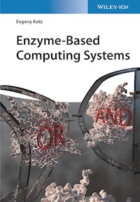
Enzyme‐based logic gates are usually realized through relatively simple enzyme‐catalyzed reactions [19, 20] (Figure 1.3). Rapid progress in enzyme‐based information processing systems has resulted in the design of biocatalytic cascades mimicking various Boolean logic gates, including AND [52, 56–59], OR [59, 60], NAND [61], NOR [57, 61], CNOT [62], XOR [57, 59, 63–65], INHIB [57, 59], Identity [57], and Inverter [57] gates. In order to digitalize chemical processes, the reacting species considered as logic input signals were applied at two levels of their concentrations: their physical absence (zero concentration) was defined as logic 0 input, while logic 1 input was defined as experimentally optimized and conveniently high concentration, thus allowing significant separation in the produced output signals when inputs 0 and 1 were applied in different combinations. Depending on specific needs set by applications, the input signals were defined as variable concentrations of substrates and/or cofactors reacting with enzymes [57] or different concentrations of the biocatalytic enzymes added to a “soup” of substrates/cofactors being ready to react with the enzymes [59]. The non‐variable part of the system was considered as a “machinery” operating with the variable input signals applied in various combinations. Multistep biocatalytic cascades activated by several (more than two) input signals have been assembled to mimic logic circuits composed of concatenated logic gates [66–69]. Various reaction cascades have been designed to mimic different combinations of concatenated logic gates; however, they usually do not include more than three or four logic steps. Due to noise formation and amplification through the reaction steps, the number of logic steps is limited, and theoretical estimation limits the system complexity by approximately 10 logic steps (which have never been realized experimentally in those enzyme‐biocatalyzed reactions) [70]. Complex branched biocatalytic reactions realized in flow cell systems have been used to mimic operation of reversible logic gates, such as Feynman gate, Double Feynman gate, Toffoli gate, Peres gate, and Fredkin gate [71–74].
Figure 1.3 Enzyme‐based Boolean logic gates – artistic vision.
Source: Katz 2018 [2]. Adapted with permission of John Wiley and Sons.


