47,99 €
Mehr erfahren.
- Herausgeber: John Wiley & Sons
- Kategorie: Wissenschaft und neue Technologien
- Sprache: Englisch
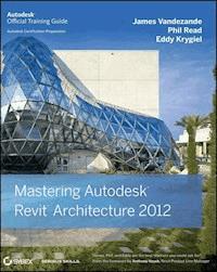
Complete and thorough update to this Autodesk Official TrainingGuide! With pages of focused discussions, detailed exercises, in-depthcoverage, and compelling examples, this comprehensive guide showsyou how to implement and use Revit Architecture with spectacularresults. You?ll learn how use the interface, how to createfantastic building designs with Revit, how to produce soliddocumentation?even how to go direct to fabrication with Revit. AnAutodesk Official Training Guide, this thorough reference andtutorial also helps you prepare for Autodesk's Certified Associateand Certified Professional exams. * Gets you quickly productive with Revit Architecture?s featuresand functions * Shows you how to document, detail, annotate, and present yourdesigns * Helps you improve workflows with worksharing andcollaboration * Prepares you for the Revit Architecture 2011 CertifiedAssociate and Certified Professional Exams * Gives contractors the essentials of modeling * Explores using Revit for film and stage Mastering Autodesk Revit Architecture is the ultimatereal-world reference on this exciting software.
Sie lesen das E-Book in den Legimi-Apps auf:
Seitenzahl: 1486
Veröffentlichungsjahr: 2011
Ähnliche


Table of Contents
Cover
Title
Copyright
Publisher's Note
Dedication
Acknowledgments
About the Authors
Foreword
Introduction
Who Should Read This Book
What You Will Learn
The Mastering Series
Contacting the Authors
Part 1: Fundamentals
Chapter 1: Introduction: The Basics of BIM
Leveraging the Model
How BIM Affects Firm Culture
Focusing Your Investment in BIM
The Bottom Line
Chapter 2: Principles of Revit
Project Organization
Interface Organization
The Bottom Line
Chapter 3: The Basics of the Revit Toolbox
Selecting, Modifying, and Replacing Elements
Editing Elements Interactively
Exploring Other Editing Tools
Modeling Site Context
The Bottom Line
Part 2: The Revit Workflow
Chapter 4: Configuring Templates and Standards
Introducing Project Templates
Customizing Project Settings for Graphic Quality
Efficient View Management
Creating Custom Annotations
Starting a Project with a Custom Template
Strategies for Managing Templates
The Bottom Line
Chapter 5: Managing a Revit Project
Understanding a BIM Workflow
Staffing for BIM
Working in a Large Team
Quality Control and BIM
The Bottom Line
Chapter 6: Understanding Worksharing
Understanding Worksharing Basics
Using Worksharing in Your Project
Managing Workflow with Worksets
Understanding Element Ownership in Worksets
The Bottom Line
Chapter 7: Working with Consultants
Preparing for Collaboration
Coordination in Revit
The Bottom Line
Chapter 8: Interoperability: Working Multiplatform
The BIM Curve
Overview of Importing
Importing 2D Data
Importing 3D Data
Overview of Exporting
Exporting 2D CAD Data
Exporting 3D Model Data
The Bottom Line
Part 3: Modeling and Massing for Design
Chapter 9: Advanced Modeling and Massing
Massing UI and Functionality
Intuitive Massing
Formula-Driven Massing
The Bottom Line
Chapter 10: Conceptual Design and Sustainability
Sustainable Design Concepts
Using Schedules
Sunshading and Solar Paths
Energy Modeling
Daylighting
The Bottom Line
Chapter 11: Designing with Design Options and Groups
Associating Phasing to Geometry, Views, and Project Settings
Using Phasing to Apply the Element of Time
Creating and Using Groups
Making Design Options for Design Iteration
The Bottom Line
Chapter 12: Visualization
The Role of Visualization
Analytic Visualization
Photorealistic Visualization
Visualization Sequence and Workflow
The Bottom Line
Part 4: Extended Modeling Techniques
Chapter 13: Walls and Curtain Walls
Using Extended Modeling Techniques for Basic Walls
Creating Stacked Walls
Creating Simple Curtain Walls
Creating Complex Curtain Walls
The Bottom Line
Chapter 14: Floors, Ceilings, and Roofs
Understanding Floor Modeling Methods
Modeling Floor Finishes
Creating Ceilings
Understanding Roof Modeling Methods
Advanced Shape Editing for Floors and Roofs
The Bottom Line
Chapter 15: Family Editor
Understanding the Family Editor
Creating a Family Component
Using Advanced Modeling Techniques
Building a Shelf Using Formulas and Type Catalogs
The Bottom Line
Chapter 16: Stairs and Railings
How to Approach Stairs and Railings
Key Components of Stairs and Railings
Creating Railings
Stairs In and Out of the Box
The Bottom Line
Part 5: Documentation
Chapter 17: Detailing Your Design
Creating Details
Adding Detail Components to Families
Learning Efficient Detailing
The Bottom Line
Chapter 18: Documenting Your Design
Documenting Plans
Creating Schedules and Legends
Using Details from Other Files
Laying Out Sheets
The Bottom Line
Chapter 19: Annotating Your Design
Annotating with Text and Keynotes
Annotating with Tags
Adding Dimensions
Annotating with Project and Shared Parameters
The Bottom Line
Chapter 20: Presenting Your Design
Adding Color Fill Legends
Presenting with 3D Views
Editing Viewport Types
The Bottom Line
Part 6: Construction and Beyond
Chapter 21: Making Projects Parametric
Generic Model Outline Families
Sustainability Analysis
Mass and Mass Floor Schedules for Area Analysis
Curtain Systems on Mass Faces
Occupancy, Egress, and Plumbing Calculations
Documentation
Finding Additional Resources
The Bottom Line
Chapter 22: Revit in Construction
Adding Revisions to Your Project
Using Digital Markups
Revit for the Builder
Modeling for Construction
The Bottom Line
Chapter 23: Revit in the Classroom
Introduction to Singapore Polytechnic
Final Design Project: School of Fashion Design
Student Showcase
The Bottom Line
Chapter 24: Revit and Virtualization
What Is Virtualization?
Advantages of Virtualization
Creating Virtual Machines
The Bottom Line
Chapter 25: Getting Acquainted with the Revit API
Introducing the Revit API
Revit API Project Types
External Utility Installation
Selecting Your Development Environment
The Sample Project
Additional API Resources
The Bottom Line
Chapter 26: Revit for Film and Stage
Revit in the Film Industry
Using Revit in the Design-to-Production Process
Previsualization in Revit
Best Practices for Film and Stage
Industry Examples
The Bottom Line
Appendices
Appendix A: The Bottom Line
Chapter 1: Introduction: The Basics of BIM
Chapter 2: Principles of Revit
Chapter 3: The Basics of the Revit Toolbox
Chapter 4: Configuring Templates and Standards
Chapter 5: Managing a Revit Project
Chapter 6: Understanding Worksharing
Chapter 7: Working with Consultants
Chapter 8: Interoperability: Working Multiplatform
Chapter 9: Advanced Modeling and Massing
Chapter 10: Conceptual Design and Sustainability
Chapter 11: Designing with Design Options and Groups
Chapter 12: Visualization
Chapter 13: Walls and Curtain Walls
Chapter 14: Floors, Ceilings, and Roofs
Chapter 15: Family Editor
Chapter 16: Stairs and Railings
Chapter 17: Detailing Your Design
Chapter 18: Documenting Your Design
Chapter 19: Annotating Your Design
Chapter 20: Presenting Your Design
Chapter 21: Making Projects Parametric
Chapter 22: Revit in Construction
Chapter 23: Revit in the Classroom
Chapter 24: Revit and Virtualization
Chapter 25: Getting Acquainted with the Revit API
Chapter 26: Revit for Film and Stage
Appendix B: Tips, Tricks, and Troubleshooting
Optimizing Performance
Using Best Practices
Fixing File Corruption
Learning Tips and Shortcuts
Additional Resources
Appendix C: Revit Certification
Index
Mastering Revit Architecture Project Gallery
Kansas State University
HOK
Austin Architects
Gensler
Beck Architecture
Perkins + Will
Centerbrook
End User License Agreement
List of Tables
Chapter 10: Conceptual Design and Sustainability
Table 10-1: Footcandle readings
Chapter 25: Getting Acquainted with the Revit API
Table 25-1: .addin Manifest File Tags and Descriptions
Appendix C: Revit Certification
Table C-1: Certified Associate Exam topics and objectives
Table C-2: Certified Professional Exam topics and objectives
List of Illustrations
Chapter 1: Introduction: The Basics of BIM
Figure 1-1: Design opportunities supported by BIM
Figure 1-2: An example of rapid prototyping using BIM data
Figure 1-3: Even 2D views can evolve to illustrate and analyze spatial properties.
Figure 1-4: Construction documentation can begin to transform from 2D to 3D.
Figure 1-5: Two different methods of utilizing 3D presentation views
Figure 1-6: A still from an animation showing accurate physical conditions for the project
Figure 1-7: BIM environmental analysis time comparison
Figure 1-8: Daylighting overlay from 3ds Max Design
Figure 1-9: Two extremes of adoption
Figure 1-10: Late adoption
Figure 1-11: Intermediate adoption
Figure 1-12: Early adoption
Figure 1-13: Happiness vs. time in technological adoption
Figure 1-14: Understanding replication vs. innovation
Chapter 2: Principles of Revit
Figure 2-1: Revit organization chart
Figure 2-2: Datum in Revit
Figure 2-3: Converting datum level to view level
Figure 2-4: All project-level datum
Figure 2-5: Controlling the analytic extents of datum
Figure 2-6: Controlling the extents of datum
Figure 2-7: Analytic (3D) datum extents
Figure 2-8: Graphic (2D) datum extents
Figure 2-9: Editing the wall’s profile
Figure 2-10: Overlapping walls
Figure 2-11: Cutting geometry
Figure 2-12: Finished wall
Figure 2-13: Concentric walls
Figure 2-14: Datum and walls in context
Figure 2-15: Finished wall
Figure 2-16: Perspective view
Figure 2-17: Copied walls
Figure 2-18: Finished wall
Figure 2-19: Wall and reference plane
Figure 2-20: Setting the reference plan
Figure 2-21: Revolving the sketch
Figure 2-22: Cutting with void
Figure 2-23: Finished walls
Figure 2-24: Selecting a family template
Figure 2-25: Types of parameters
Figure 2-26: Instance parameters of a wall
Figure 2-27: Type parameters of a wall
Figure 2-28: Visibility graphics
Figure 2-29: Plan view instance parameters
Figure 2-30: Creating plan views
Figure 2-31: Duplicating existing views
Figure 2-32: Duplicating views from the Project Browser
Figure 2-33: View Range dialog box
Figure 2-34: Crop region
Figure 2-35: Hiding the crop when printing
Figure 2-36: Elevation tag orientation
Figure 2-37: Creating additional elevations
Figure 2-38: Elevation extents
Figure 2-39: Section types
Figure 2-40: Section properties and extents
Figure 2-41: Detail sections in plan view
Figure 2-42: Detail sections in section view
Figure 2-43: Callout types
Figure 2-44: Detail callout
Figure 2-45: Floor Plan callout
Figure 2-46: Drafting view reference
Figure 2-47: Types of legends
Figure 2-48: Legend components
Figure 2-49: Creating keynote legends
Figure 2-50: Schedule types
Figure 2-51: Creating a schedule
Figure 2-52: 3D view types
Figure 2-53: Setting the work plane
Figure 2-54: Dimensions in 3D orthographic views
Figure 2-55: Setting eye and target origin
Figure 2-56: Modifying the view size and field of view
Figure 2-57: Far Clip Offset
Figure 2-58: Far Clip Offset is too shallow.
Figure 2-59: Selecting Show Camera
Figure 2-60: Extending the Far Clip Offset
Figure 2-61: Section box
Figure 2-62: Only user-created worksets are visible by default.
Figure 2-63: Elements assigned to user-defined worksets
Figure 2-64: Revit 2012 user interface
Figure 2-65: Application menu
Figure 2-66: Quick Access toolbar
Figure 2-67: Adding commands to the QAT
Figure 2-68: Customizing the QAT
Figure 2-69: InfoCenter
Figure 2-70: Properties palette
Figure 2-71: Project Browser
Figure 2-72: Project Browser’s type properties
Figure 2-73: Status bar
Figure 2-74: Drawing area
Figure 2-75: Working sheet view
Figure 2-76: View Control Bar
Figure 2-77: Realistic option
Figure 2-78: Graphic Display Options dialog box
Figure 2-79: Ghost Surfaces option
Figure 2-80: Ghost surfaces
Figure 2-81: Viewer option on the Work Plane panel
Figure 2-82: Sketch mode with active work plane
Figure 2-83: ViewCube
Figure 2-84: ViewCube options
Figure 2-85: ViewCube options
Figure 2-86: Navigation bar
Figure 2-87: The Revit ribbon
Figure 2-88: There are nine tabs in the ribbon.
Figure 2-89: Home tab
Figure 2-90: Insert tab
Figure 2-91: Annotate tab
Figure 2-92: Structure tab
Figure 2-93: Massing & Site tab
Figure 2-94: Collaborate tab
Figure 2-95: View tab
Figure 2-96: Manage tab
Figure 2-97: Modify tab
Figure 2-98: Contextual tabs
Figure 2-99: Panels identify areas of grouped functionality.
Figure 2-100: Options Bar
Chapter 3: The Basics of the Revit Toolbox
Figure 3-1: The right end of the Modify tab changes based on the element that is selected.
Figure 3-2: Use the Filter dialog box to fine-tune your selections.
Figure 3-3: The new Properties palette contains the Type Selector and is used to set view properties.
Figure 3-4: Use the Properties palette to filter selection sets.
Figure 3-5: Run recent commands from the context menu.
Figure 3-6: Drag or click the blue grip to change the reference of the temporary dimension.
Figure 3-7: The Temporary Dimension Properties dialog box lets you define default behaviors based on your modeling needs.
Figure 3-8: Once an object is selected, it can be set to move with nearby elements.
Figure 3-9: The flip arrow is another way to reorient an element. For walls, it is always found on the exterior side.
Figure 3-10: The sink, toilet, and bath fixtures are mirrored about the centerline of the chase wall.
Figure 3-11: The Move To 2nd option is used in the Array tool to set a fixed distance between instances.
Figure 3-12: This array uses the Move To Last option and fills instances between the first and last instances.
Figure 3-13: Elements will autorotate in a radial array.
Figure 3-14: You can use the Align tool for lining up edges of windows in a façade.
Figure 3-15: Extend walls to references by picking the target (1), then the wall to extend (2).
Figure 3-16: Using the Split tool with the Delete Inner Segment option checked
Figure 3-17: Use Offset with Tab-select to copy a chain of elements
Figure 3-18: A door constrained to a wall can’t be moved independently of the wall.
Figure 3-19: Deleting a constrained dimension generates an alert.
Figure 3-20: Intersections at Level 2 have been joined.
Figure 3-21: Additional actions are available when pasting elements.
Figure 3-22: Edit Pasted mode allows additional modification of pasted elements.
Figure 3-23: Paste Aligned options
Figure 3-24: Customize keyboard shortcuts for commonly used Revit commands.
Figure 3-25: A toposurface can host components such as trees, entourage, and vehicles.
Figure 3-26: Toposurfaces will appear as a solid in a 3D view only if a section box is used.
Figure 3-27: A simple toposurface created by placing points
Figure 3-28: Linked CAD file as seen in a 3D view
Figure 3-29: Select only the layers containing 3D contour information.
Figure 3-30: The sketch boundary for a subregion must be a closed loop but can overlap the edge of the toposurface.
Figure 3-31: The subregion is assigned a different material for visualization purposes.
Figure 3-32: Sketch lines that overlap the edge of the topographic surface
Figure 3-33: A split region after editing the elevation of a corner point
Figure 3-34: Compare the difference between an edited split region (left) and an edited point directly on the surface (right).
Figure 3-35: This section view illustrates how the building pad adjusts the extents of the topographic surface.
Figure 3-36: A property line can be defined in a table of distances and bearings.
Figure 3-37: Tags are applied to display the distance and bearing of each segment of the property line.
Figure 3-38: Use Tab-select to place a property area tag for all segments.
Chapter 4: Configuring Templates and Standards
Figure 4-1: Starting a new project template from scratch
Figure 4-2: The Object Styles dialog box gives you graphic control of all Revit categories and their subcategories.
Figure 4-3: Customizing the cut display of geometry in a family
Figure 4-4: Model line weights vary depending on the view scale.
Figure 4-5: This dialog box displays all line patterns in the project.
Figure 4-6: Line patterns consist of dashes, spaces, and dots.
Figure 4-7: Line styles consist of weight, color, and pattern.
Figure 4-8: Materials define the surface and cut patterns, color, and render material of the elements.
Figure 4-9: Manage material properties using the MaterialsEditor.
Figure 4-10: Use identity data to classify, find, tag, and schedule materials.
Figure 4-11: Fill patterns are defined separately for drafting and model representations.
Figure 4-12: The CMU wall has both a drafting pattern (cut) and a model pattern (surface) defined.
Figure 4-13: From left to right: Orient To View, Keep Readable, and Align With Element
Figure 4-14: From left to right: simple fill pattern, simple fill pattern with the crosshatch option selected, and a custom fill pattern
Figure 4-15: The New Pattern dialog box displays the imported PAT file in the Custom group.
Figure 4-16: Select criteria for assigning a color scheme to a view.
Figure 4-17: Edit color schemes to add predefined values, colors, and fill patterns.
Figure 4-18: Select from predefined values in the Properties dialog box of a room.
Figure 4-19: Color-filled plans can utilize predefined values in templates.
Figure 4-20: Accessing browser organization settings in the ribbon
Figure 4-21: Use view parameters to create folders in the Project Browser.
Figure 4-22: Create custom project parameters for additional view organization options.
Figure 4-23: Customized browser organizations can make larger projects easier to navigate.
Figure 4-24: Filter rules applied to walls for fire ratings
Figure 4-25: View Templates dialog box
Figure 4-26: Reapplying default templates to views on sheets
Figure 4-27: The Tags dialog box shows loaded annotation families assigned to selected categories.
Figure 4-28: A custom room tag showing room name, number, area, and volume
Figure 4-29: Custom door tag with parametric label
Figure 4-30: Adding more than one parameter to a single label
Figure 4-31: Actual door sizes comprise the custom tags applied to doors.
Figure 4-32: Section tag system family properties
Figure 4-33: Samples of graphic content as supplied by Autodesk
Figure 4-34: Custom section tag
Figure 4-35: Place labels for Detail Number and Sheet Number.
Figure 4-36: Draw the outline of the filled region to form the section arrow.
Figure 4-37: Custom section mark after the section is placed on a sheet
Figure 4-38: Custom callout annotation (left); custom callout annotation associated with callout boundary (right)
Figure 4-39: Define the custom linework and sheet number for the elevation mark body.
Figure 4-40: Custom elevation pointer composed of lines, filled region, and labels
Figure 4-41: The nested pointer family is placed four times in the head family.
Figure 4-42: A customized elevation tag for interior elevations
Figure 4-43: Change the path to your default template.
Figure 4-44: Additive template approach
Figure 4-45: Subtractive template approach
Figure 4-46: Select categories to be transferred between projects.
Figure 4-47: Transferring project standards with duplicate types
Figure 4-48: Insert Views can be used to transfer an entire sheet of drafting views into your project.
Figure 4-49: Insert 2D Elements dialog box
Chapter 5: Managing a Revit Project
Figure 5-1: A CAD-based workflow
Figure 5-2: A BIM workflow
Figure 5-3: The traditional method of design review
Figure 5-4: An integrated approach to design review
Figure 5-5: The integrated design model
Figure 5-6: From abstraction to virtualization
Figure 5-7: Staffing in BIM
Figure 5-8: BIM provides the most leverage when it is implemented earlier in the design.
Figure 5-9: Roles over the project cycle
Figure 5-10: Turning worksets on and off
Figure 5-11: The Shell workset turned off (left) and turned on (right)
Figure 5-12: The Purge Unused dialog box
Figure 5-13: Filtering out views on sheets
Figure 5-14: Sorting the schedule by sheet name
Figure 5-15: The finished schedule
Figure 5-16: Specify the sorting and grouping options for the multicategory schedule.
Figure 5-17: The multicategory schedule shows all elements in the project.
Figure 5-18: Use the Footer option to show a count of each keynote.
Figure 5-19: The Keynote Legend view
Figure 5-20: The Warnings dialog box
Figure 5-21: Exporting the warnings
Chapter 6: Understanding Worksharing
Figure 6-1: The worksharing concept
Figure 6-2: The Collaborate tab
Figure 6-3: The Worksets button
Figure 6-4: Activating worksharing
Figure 6-5: The Worksets dialog box
Figure 6-6: Workset organization for the Jenkins Building
Figure 6-7: Save As dialog box
Figure 6-8: File Save Options dialog box
Figure 6-9: Relinquishing permissions
Figure 6-10: Opening a local file for the first time
Figure 6-11: Workset and element ownership
Figure 6-12: Changing the default username
Figure 6-13: Changing the active workset
Figure 6-14: Changing the active workset from the status bar
Figure 6-15: Synchronize With Central command on the ribbon
Figure 6-16: Synchronize With Central dialog box
Figure 6-17: Using the Synchronize Now option
Figure 6-18: Changes Not Saved dialog box
Figure 6-19: Using Reload Latest
Figure 6-20: Moving objects between worksets
Figure 6-21: The Furniture Workset
Figure 6-22: Making an element editable
Figure 6-23: Making an element editable using the context menu
Figure 6-24: Placing a request for permission
Figure 6-25: Editing Request Placed dialog box
Figure 6-26: Permission granted
Figure 6-27: Permission notification
Figure 6-28: Editing Requests dialog box
Figure 6-29: Relinquish All Mine
Figure 6-30: Saving to the central file
Figure 6-31: Disabling worksharing
Figure 6-32: Controlling workset visibility
Figure 6-33: Selecting the starting view
Figure 6-34: Changing the workset assignment
Figure 6-35: Workset visualization
Figure 6-36: Ownership Status tab
Figure 6-37: Individual Owners tab
Figure 6-38: Updates tab
Figure 6-39: Worksets tab
Figure 6-40: Using the Updates slider
Figure 6-41: This dialog box indicates that you have permissions that need to be reconciled.
Chapter 7: Working with Consultants
Figure 7-1: BIM data exchanges according to NBIMS
Figure 7-2: The relationships of interdisciplinary coordination
Figure 7-3: Suggestions for collaboration tools to be used between disciplines
Figure 7-4: Linked files must use the same platform version, and all worksharing team members should use the same build.
Figure 7-5: Click the Help button flyout and select About to find the build of your Revit software.
Figure 7-6: Diagram of the relationship between project base points and shared coordinates in linked models
Figure 7-7: Creating multiple locations for a single linked model
Figure 7-8: The project base point and survey point are found under Site in Visibility/Graphic Overrides.
Figure 7-9: The survey point can be considered similar to a real-world geodetic survey marker.
Figure 7-10: Using tiled windows helps you examine the effect of project and shared coordinates.
Figure 7-11: Determining the reference type of linked Revit models
Figure 7-12: Open a worksharing project detached from its central file.
Figure 7-13: Save option to establish a new central file
Figure 7-14: Relinquish all user-created worksets when saving a file that has been detached from central.
Figure 7-15: Schematic representation of a complex project assembled with multiple linked models
Figure 7-16: Enable all custom display settings for a linked RVT file.
Figure 7-17: Enable custom display settings for model categories of a linked RVT file.
Figure 7-18: Element tabs available for Copy/Monitor in Revit Architecture
Figure 7-19: The Copy/Monitor Options dialog box allows customization for intelligent collaboration.
Figure 7-20: Additional copy parameters can be applied to each element category.
Figure 7-21: The Coordination Review dialog box lists inconsistencies in monitored elements.
Figure 7-22: Coordination Review detects changes to monitored elements.
Figure 7-23: D coordination model in Navisworks Manage
Figure 7-24: Select categories to be included in an interference report.
Figure 7-25: Results of an interference check are displayed in the Interference Report window.
Chapter 8: Interoperability: Working Multiplatform
Figure 8-1: The BIM curve shows loss of data without interoperability at project milestones.
Figure 8-2: Defining settings for imported DWG/DXF line weights
Figure 8-3: Options available for import/link
Figure 8-4: Querying objects within a linked CAD file
Figure 8-5: Controlling visibility of layers within imported objects
Figure 8-6: Changing the graphic appearance of imported layers via object styles
Figure 8-7: Existing CAD data integrated with the Revit model
Figure 8-8: Creating a view as a reference to a drafting view
Figure 8-9: Callout created to reference a drafting view containing a linked CAD detail
Figure 8-10: Curves for a complex surface in Rhino
Figure 8-11: Completed complex surface in Rhino
Figure 8-12: Complex surface linked as an in-place mass
Figure 8-13: Roof By Face applied to the mass with linked SAT geometry
Figure 8-14: Completed roof with tops of walls attached
Figure 8-15: DGN structural model linked into Revit
Figure 8-16: Export commands accessed by clicking the Application menu
Figure 8-17: First view of Export Settings dialog box
Figure 8-18: Viewing available export sets in the model
Figure 8-19: Create a new export list.
Figure 8-20: Showing all views and sheets in the model
Figure 8-21: Adding views/sheets to the export list
Figure 8-22: Accessing export layer settings on the DWG Properties tab
Figure 8-23: Industry standard layering conventions can be applied to export settings.
Figure 8-24: Exported layer names and colors can be customized for any standard.
Figure 8-25: View organization for plans to be exported
Figure 8-26: DWG properties for exporting
Figure 8-27: DWG properties for exporting
Figure 8-28: Layer properties for exporting
Figure 8-29: Modifying layer properties for exporting
Figure 8-30: Lines properties for exporting
Figure 8-31: Custom line properties for exporting
Figure 8-32: Pattern properties for exporting
Figure 8-33: Custom pattern properties for exporting
Figure 8-34: Text and font properties for exporting
Figure 8-35: Custom text and font properties for exporting
Figure 8-36: Color properties for exporting
Figure 8-37: Solid properties for exporting
Figure 8-38: Unit and coordinate properties for exporting
Figure 8-39: Unit and coordinate properties for exporting
Figure 8-40: Using the section box to expose the layers of the wall
Figure 8-41: Hide the section box to prevent it from exporting.
Figure 8-42: Completed wall study in Google SketchUp
Figure 8-43: Revit model exported to IFC format
Chapter 9: Advanced Modeling and Massing
Figure 9-1: Complex in-place wall
Figure 9-2: Wall created from in-place mass surface
Figure 9-3: Massing created in the Family Editor
Figure 9-4: Selecting Model In-Place
Figure 9-5: Selecting the Mass category
Figure 9-6: Massing & Site tab
Figure 9-7: Revit enables the Show Mass mode.
Figure 9-8: Naming the mass
Figure 9-9: Massing functionality
Figure 9-10: Cube, Pyramid, and Sphere
Figure 9-11: Separate masses in the Family Browser
Figure 9-12: Intersecting levels
Figure 9-13: Mass Floors command
Figure 9-14: Selecting all levels
Figure 9-15: Floor area faces
Figure 9-16: Creating a schedule
Figure 9-17: Scheduled fields
Figure 9-18: Volume-to-floor ratio
Figure 9-19: Surface-to-floor ratio
Figure 9-20: Completed schedule
Figure 9-21: Nonmassing form creation
Figure 9-22: Create Form option
Figure 9-23: Create Form warning
Figure 9-24: Draw panel for both model and reference lines
Figure 9-25: Model lines and reference lines
Figure 9-26: Object styles for reference lines
Figure 9-27: Option to create face or solid from reference lines
Figure 9-28: Reference line segment types
Figure 9-29: Reference line control points
Figure 9-30: Surface forms
Figure 9-31: Surfaces based on multiple splines
Figure 9-32: Single and multispline surfaces
Figure 9-33: Adding a profile
Figure 9-34: Moved profile
Figure 9-35: Using the Dissolve tool
Figure 9-36: Additional spline added
Figure 9-37: New surface form
Figure 9-38: Edited center spline
Figure 9-39: Spline-based surfaces
Figure 9-40: Surface or form option
Figure 9-41: Creating a solid from a surface
Figure 9-42: Using reference shapes to create forms
Figure 9-43: Resulting mass forms
Figure 9-44: Creating an additional level
Figure 9-45: Spline Through Points
Figure 9-46: Second Spline Through Points
Figure 9-47: Selecting Create Form
Figure 9-48: Resulting surface
Figure 9-49: Wall By Face
Figure 9-50: Resulting wall
Figure 9-51: Modified surface
Figure 9-52: Update To Face
Figure 9-53: Updated wall
Figure 9-54: Adding another Spline Through Points
Figure 9-55: Dissolving the surface
Figure 9-56: Finishing the family and updating the wall
Figure 9-57: Divide Surface tool
Figure 9-58: Divided surface
Figure 9-59: Selecting No Pattern
Figure 9-60: Selecting the Triangle (Flat) surface pattern
Figure 9-61: The result of choosing the Triangle (Flat) pattern
Figure 9-62: Partial option
Figure 9-63: Empty option
Figure 9-64: Overhanging option
Figure 9-65: Curtain Panel Pattern Based template
Figure 9-66: Panel options in the Properties tab
Figure 9-67: Triangle (Flat) template
Figure 9-68: Creating only the surface form
Figure 9-69: Options for assigning geometry
Figure 9-70: Panel assigned to mass surface
Figure 9-71: Copying the three reference points
Figure 9-72: Moving the reference points
Figure 9-73: Joining the reference points with new reference lines
Figure 9-74: Blended form
Figure 9-75: The updated components, resulting in a complex form
Figure 9-76: Voided blended panels
Figure 9-77: Revised form
Figure 9-78: Rectilinear form
Figure 9-79: Plan view of sketch
Figure 9-80: Creating a solid form
Figure 9-81: Resulting form
Figure 9-82: Face control
Figure 9-83: Edge control
Figure 9-84: Vertex control
Figure 9-85: Parallel and perpendicular control
Figure 9-86: X-ray mode
Figure 9-87: Adding an edge
Figure 9-88: Pushing the face
Figure 9-89: Pushing the edge
Figure 9-90: Pulling the edge
Figure 9-91: Adding more edges
Figure 9-92: Pulling the upper edge
Figure 9-93: Using Dissolve to remove the mass solid
Figure 9-94: Making a lofted blend from three profiles
Figure 9-95: Making a blend from two profiles
Figure 9-96: Deleting the edge
Figure 9-97: Selecting the work plane
Figure 9-98: Completing the profile
Figure 9-99: Creating the form
Figure 9-100: Creating another form
Figure 9-101: Unlocking a reference
Figure 9-102: Modifying the edge
Figure 9-103: Adding a profile
Figure 9-104: Completed mass
Figure 9-105: Using shape handles
Figure 9-106: Finished form
Figure 9-107: Adding a solid
Figure 9-108: Converting a solid to a void
Figure 9-109: Cutting the void
Figure 9-110: Starting with the Mass template
Figure 9-111: Graphic display options
Figure 9-112: Massing UI
Figure 9-113: Selecting the Make Surface From Closed Loops option
Figure 9-114: Creating the mass
Figure 9-115: Adding dimensions
Figure 9-116: Associating parameters
Figure 9-117: Creating parameters
Figure 9-118: Completed parameters
Figure 9-119: Creating formulas
Figure 9-120: Proportional form
Figure 9-121: Adjusting the height numerically
Figure 9-122: Adjusting the height intuitively
Figure 9-123: Adding a second form
Figure 9-124: Associative parameters
Figure 9-125: Proportional forms
Figure 9-126: Modifying parameters
Figure 9-127: Generic Model template
Figure 9-128: Message box explaining you can’t change the category
Figure 9-129: First reference line
Figure 9-130: Second reference line
Figure 9-131: Creating a blend
Figure 9-132: Setting the work plane
Figure 9-133: Selecting the upper reference line
Figure 9-134: Bottom with dimensions
Figure 9-135: Use these instance parameters.
Figure 9-136: Setting the work plane
Figure 9-137: Top width parameters and sketch
Figure 9-138: Adding the height parameter
Figure 9-139: Instance parameter for the height
Figure 9-140: Twisting the blend with reference lines
Figure 9-141: Angular parameters
Figure 9-142: Turning a solid into a void
Figure 9-143: The resulting void blend
Figure 9-144: Selecting the Sweep function
Figure 9-145: Using the Pick Path tool
Figure 9-146: Selecting the edges of the blend
Figure 9-147: Selecting the Edit Profile option
Figure 9-148: Adding parameters to the profile width and height
Figure 9-149: Finished mass
Figure 9-150: Naming the mass
Figure 9-151: Changing parameter values
Figure 9-152: Adding levels that extend across the elevation of your massing
Figure 9-153: Floor area faces
Figure 9-154: Adding pattern-based components
Figure 9-155: Perspective views
Figure 9-156: Rendering of the generic massing project
Figure 9-157: Conceptual massing template
Figure 9-158: Family Types dialog box
Figure 9-159: Using reference lines
Figure 9-160: Dimensioned reference lines
Figure 9-161: Ignore this warning.
Figure 9-162: Moving the point element
Figure 9-163: Adding a parameter to the point element
Figure 9-164: The South elevation will look like this.
Figure 9-165: Selecting Always next to Show Reference
Figure 9-166: The reference planes will now be visible.
Figure 9-167: Setting the rotation angle
Figure 9-168: Creating the second sketch
Figure 9-169: Reference lines and point elements
Figure 9-170: Testing our form and instance parameters
Figure 9-171: Increasing the WCPL instance parameter
Figure 9-172: Increasing the APL parameter
Figure 9-173: Flexing the parameters
Figure 9-174: Adding patterns to the face of your mass
Figure 9-175: Floor area faces
Chapter 10: Conceptual Design and Sustainability
Figure 10-1: Adding fields to the schedule
Figure 10-2: Finishing the calculated value
Figure 10-3: Adding filters to the schedule
Figure 10-4: The Concrete Takeoff schedule
Figure 10-5: Adding the conceptual mass to the Jenkins model
Figure 10-6: Selecting floors
Figure 10-7: Mass floors have been added to the mass.
Figure 10-8: Creating the new calculated value
Figure 10-9: The finished schedule
Figure 10-10: The Jenkins building during the equinox
Figure 10-11: The Jenkins building during the summer solstice
Figure 10-12: Summer solstice (left) and winter solstice (right)
Figure 10-13: The Graphic Display Options dialog box
Figure 10-14: The Sun Settings dialog box
Figure 10-15: Set your project’s location in the Location Weather And Site dialog box.
Figure 10-16: The finished camera view with Still sun settings applied
Figure 10-17: Exterior view from the south looking north
Figure 10-18: View from inside the Living/Dining area
Figure 10-19: Interior view with sun and phase settings applied correctly
Figure 10-20: Access the Preview Solar Study command by selecting the Sun Path button.
Figure 10-21: Length/Format dialog box
Figure 10-22: Choose a video compression codec.
Figure 10-23: Adjust the size of the 3D view by changing the size of the crop region.
Figure 10-24: Activating the sun path
Figure 10-25: Dynamically modifying the sun path
Figure 10-26: Energy use in the United States
Figure 10-27: The Analyze tab in the ribbon
Figure 10-28: In Energy Settings, first specify the location and weather station.
Figure 10-29: Specify assumptions for the construction type based on your mass model.
Figure 10-30: Name each analysis run for easy comparison.
Figure 10-31: The Results And Compare window
Figure 10-32: Make sure your building envelope is fully enclosed.
Figure 10-33: Placing rooms
Figure 10-34: Use the Filter tool to select only the rooms.
Figure 10-35: Modifying the room height
Figure 10-36: Opening Area And Volume Computations
Figure 10-37: Enabling volume calculations for rooms
Figure 10-38: Exporting gbXML settings
Figure 10-39: Exporting complexity settings
Figure 10-40: The Details tab allows you to examine any errors or warnings.
Figure 10-41: Clicking the warning button will display the problems related to the selected room.
Figure 10-42: Materials dialog box
Figure 10-43: Glazing material
Figure 10-44: Define an interior camera view for exporting.
Figure 10-45: Changing the unit settings per your location
Figure 10-46: The FBX Import dialog box
Figure 10-47: Lighting Analysis Assistant settings on the General and Materials tab
Figure 10-48: The Lighting tab in the Lighting Analysis Assistant
Figure 10-49: Loading the weather file in the Configure Weather Data dialog box
Figure 10-50: Setting the date and time from the imported weather data
Figure 10-51: Choose Perez All Weather as a sky model.
Figure 10-52: Click Create A Light Meter and define a plane in a plan view.
Figure 10-53: Creating the light meter grid
Figure 10-54: Set Final Gather to 3.
Figure 10-55: The final analysis
Figure 10-56: A rendered daylighting scene
Chapter 11: Designing with Design Options and Groups
Figure 11-1: Wall joins in the same phase
Figure 11-2: Joins across different phases may not always clean up as intended.
Figure 11-3: Creating a construction sequence instance parameter for project geometry
Figure 11-4: Applying filters by parameter
Figure 11-5: View filters and graphic overrides settings
Figure 11-6: Using parameters and view filters to override graphics
Figure 11-7: Changing the phase of geometry
Figure 11-8: The phase of a room may not be changed after placement.
Figure 11-9: Changing the phase of a view
Figure 11-10: The Phasing dialog box
Figure 11-11: Creating additional project phases
Figure 11-12: Assigning available phases
Figure 11-13: The Phase Filters tab, with seven predefined phases
Figure 11-14: Setting a filter override
Figure 11-15: The Graphic Overrides tab
Figure 11-16: Four generic walls
Figure 11-17: Default shaded overrides for phasing
Figure 11-18: Default Graphic Overrides settings
Figure 11-19: Default shaded override for existing materials
Figure 11-20: Overriding the Shading value
Figure 11-21: Finished shading values
Figure 11-22: Phase Filter options
Figure 11-23: Show All and New Construction
Figure 11-24: Shaded plan view of phased elements
Figure 11-25: Existing phase only
Figure 11-26: Show Previous + Demo
Figure 11-27: Show Previous Phase
Figure 11-28: Show Previous + New elements
Figure 11-29: Showing Existing and all New elements
Figure 11-30: Existing to Remain, Proposed, and Temporarily Proposed elements
Figure 11-31: Show Demo + New
Figure 11-32: Turning off the display of demolished elements from a previous phase
Figure 11-33: Showing only New and Temporary elements
Figure 11-34: Showing only New elements
Figure 11-35: Showing finished conditions
Figure 11-36: Four walls and dimensions
Figure 11-37: Creating the model and attached detail group
Figure 11-38: Copied group
Figure 11-39: Attached Detail Group Placement dialog box
Figure 11-40: Identical groups
Figure 11-41: Adding a door outside of Group mode
Figure 11-42: Group Edit mode
Figure 11-43: Finished group
Figure 11-44: Duplicating a group
Figure 11-45: Modifying the second group
Figure 11-46: Insertion points in different groups
Figure 11-47: Relocating insertion points
Figure 11-48: Exchanged groups
Figure 11-49: Group conflicts
Figure 11-50: Adding a new door
Figure 11-51: Selecting elements in groups
Figure 11-52: Excluded elements not shown
Figure 11-53: Saving groups
Figure 11-54: Loading modified groups
Figure 11-55: Retaining excluded group elements
Figure 11-56: Adding groups as links
Figure 11-57: Wall joins between links vs. groups
Figure 11-58: Binding links
Figure 11-59: Resolved wall graphics
Figure 11-60: Avoid attaching with groups.
Figure 11-61: Resolving attachments warning
Figure 11-62: Starting design options
Figure 11-63: Design Options panel
Figure 11-64: Creating an option set and two options
Figure 11-65: Adding elements to option sets
Figure 11-66: Selecting the option
Figure 11-67: Adding elements to an option set using the status bar
Figure 11-68: Another way to select and edit Design Options
Figure 11-69: Edit Option mode
Figure 11-70: The Design Options panel displays Automatic.
Figure 11-71: Locking the view to a design option
Figure 11-72: Select the option set and click Delete.
Figure 11-73: Click Yes at this warning.
Figure 11-74: You can deselect views that you want to retain.
Figure 11-75: Delete Option Set warning
Figure 11-76: Click the Make Primary button.
Chapter 12: Visualization
Figure 12-1: Default material rendering
Figure 12-2: Abstract rendering
Figure 12-3: Phasing settings
Figure 12-4: Material assignments
Figure 12-5: Assigning abstract material
Figure 12-6: Phase and phase filter
Figure 12-7: Filters dialog box
Figure 12-8: Default view
Figure 12-9: Selecting the Filters tab
Figure 12-10: Creating the filter, category, and filter rules
Figure 12-11: Our added filter
Figure 12-12: Graphic overrides
Figure 12-13: Applied filter in Shaded view
Figure 12-14: Applied filter in Hidden Line view
Figure 12-15: Multicategory selection
Figure 12-16: User-defined instance parameters
Figure 12-17: Filter parameters
Figure 12-18: Graphic overrides for the Not In Contract filter
Figure 12-19: Instance parameters
Figure 12-20: Not In Contract graphic override
Figure 12-21: Identifying generic elements
Figure 12-22: Generic host element filter
Figure 12-23: Visual sun path
Figure 12-24: Sun path properties at 100 percent
Figure 12-25: Sun path properties at 200 percent
Figure 12-26: Activating the sun path
Figure 12-27: Editing the sun path
Figure 12-28: Sun settings
Figure 12-29: Animation export path
Figure 12-30: Animation length and format
Figure 12-31: D and orthographic View Control bar
Figure 12-32: Perspective View Control bar
Figure 12-33: Level of detail
Figure 12-34: View scale-to-detail level
Figure 12-35: Nonidentical views
Figure 12-36: Detail level of chair
Figure 12-37: Visual styles
Figure 12-38: Wireframe view
Figure 12-39: Hidden Line view
Figure 12-40: Shaded view
Figure 12-41: Shaded With Edges view
Figure 12-42: Consistent Colors view
Figure 12-43: Realistic view
Figure 12-44: Graphic Display Options
Figure 12-45: Ghost Surfaces
Figure 12-46: Shadows On/Off
Figure 12-47: Default Shadows On
Figure 12-48: Graphic Display Options dialog box
Figure 12-49: Choosing Sunlight From Top Left
Figure 12-50: Increased Sun Intensity setting
Figure 12-51: Softened view
Figure 12-52: Decreased Cast Shadows value
Figure 12-53: Softened shadows
Figure 12-54: Silhouette Style
Figure 12-55: No silhouettes vs. Wide Lines silhouettes
Figure 12-56: Background settings
Figure 12-57: Ambient light and shadows
Figure 12-58: Activating ambient light and shadows
Figure 12-59: Ambient lighting with edges
Figure 12-60: Saving the view template
Figure 12-61: View Templates dialog box
Figure 12-62: Activating the section box
Figure 12-63: Pulling the section box to isolate a portion of the project
Figure 12-64: Poche settings
Figure 12-65: Regions between host elements are shown as discrete geometries.
Figure 12-66: Solid poche black
Figure 12-67: Rendering dialog box
Figure 12-68: Quality settings
Figure 12-69: Draft settings
Figure 12-70: Best settings
Figure 12-71: Output Settings
Figure 12-72: Printer settings
Figure 12-73: Rendered project
Figure 12-74: Quality render times
Figure 12-75: Orthographic vs. perspective view
Figure 12-76: Lock view settings
Figure 12-77: Placing the camera
Figure 12-78: Selecting Show Camera
Figure 12-79: Aspect ratio
Figure 12-80: Crop Region Size dialog box
Figure 12-81: Navigational Wheel
Figure 12-82: Creating the walkthrough
Figure 12-83: Finished camera path
Figure 12-84: Going to the camera view
Figure 12-85: Walkthrough properties
Figure 12-86: Setting the aspect ratio
Figure 12-87: Setting the graphic display options
Figure 12-88: Tiled camera and views
Figure 12-89: Edit Walkthrough option
Figure 12-90: Key Frame Editor
Figure 12-91: Camera path and controls
Figure 12-92: Export menu
Figure 12-93: Graphic format controls
Figure 12-94: Default frame count
Figure 12-95: Increasing the frame count
Figure 12-96: Viewing our project in Hidden Line view
Figure 12-97: Ghost surfaces
Figure 12-98: Abstract phasing setting
Figure 12-99: Rendering settings for our view
Figure 12-100: Sun Only rendering
Figure 12-101: Ceiling settings
Figure 12-102: Ceilings added
Figure 12-103: Rendering Settings dialog box
Figure 12-104: Lights in ceiling
Figure 12-105: Light groups
Figure 12-106: Creating light groups
Figure 12-107: Assigning light groups
Figure 12-108: Rendering light groups
Figure 12-109: Rendering both light groups
Figure 12-110: Adding more lights
Figure 12-111: Rendering without center lights
Figure 12-112: Placing the light in top-oriented 3D Wireframe view
Figure 12-113: Conference table light
Figure 12-114: Lighting Fixtures category and subcategories
Figure 12-115: Extrusion sketch
Figure 12-116: Selecting a work plane
Figure 12-117: Align and lock
Figure 12-118: Delete the original lens geometry.
Figure 12-119: Updated light
Figure 12-120: Rendering with a lens
Figure 12-121: Creating the subcategory
Figure 12-122: Assigning the subcategory
Figure 12-123: Creating and assigning the material parameter
Figure 12-124: Deselecting the Lens subcategory
Figure 12-125: Rendered view
Figure 12-126: The workset should be turned off in other views.
Figure 12-127: Adding entourage
Figure 12-128: Rendering with material
Figure 12-129: Selecting the Paint tool
Chapter 13: Walls and Curtain Walls
Figure 13-1: The Type Properties dialog box for a wall
Figure 13-2: The Edit Assembly dialog box lets you define the construction layers of a wall type.
Figure 13-3: Layers with the same priority clean up when joined.
Figure 13-4: Two layers with the same priority but different materials. The separation between the two layers is indicated with a thin line.
Figure 13-5: Layer wrapping is a result of a coordinated approach between wall layers and hosted families such as windows.
Figure 13-6: A wall’s outer core boundary is used to define an edge of the floor.
Figure 13-7: Section detail of joined wall and floor slab
Figure 13-8: Wall functions can be assigned to different layers for exported CAD files.
Figure 13-9: Default wrapping options can be set in Edit Assembly or Type Properties.
Figure 13-10: Assign the Wall Closure parameter to a reference plane.
Figure 13-11: Sample wall with added articulation
Figure 13-12: With section view active, tools for modifying the vertical structure become active.
Figure 13-13: Splitting the exterior finish into two materials
Figure 13-14: (A) Merge vertical layers; (B) merge layers that were previously split.
Figure 13-15: Bullnose sweep added to wall assembly
Figure 13-16: Reveals have been added to the compound wall assembly.
Figure 13-17: Camera view of compound wall with reveals and sweeps
Figure 13-18: Modified wall sweep returns
Figure 13-19: Examples of wall layers extending past or within the constraints of the wall
Figure 13-20: Using the Modify button, click the padlock icon to unlock layers.
Figure 13-21: Modifying the wall layer to have a base extension
Figure 13-22: Unlocked layers can be modified in a section view by dragging or with the Align or Move tool.
Figure 13-23: Wall joins will clean up by default regardless of phasing.
Figure 13-24: Walls with disallowed joins will overlap.
Figure 13-25: Use Trim/Extend or drag wall endpoints to complete the modification.
Figure 13-26: Use the Wall Joins tool to modify intersecting wall conditions.
Figure 13-27: Various corner conditions can be chosen with the Wall Joins tool.
Figure 13-28: Stacked wall attached to an extruded roof
Figure 13-29: The sketch elevation boundary for a stacked wall instance is edited.
Figure 13-30: Manually constructed wall used to create nonvertical surfaces
Figure 13-31: The Edit Assembly dialog box for stacked walls
Figure 13-32: Inserts may not host correctly in vertically stacked walls.
Figure 13-33: Use the Pick Primary Host tool to adjust inserts in stacked walls.
Figure 13-34: Glazed dome created with a curtain system
Figure 13-35: Curtain wall with regular orthogonal grids and expressive curtain panels
Figure 13-36: Curtain wall with a few manually applied grids
Figure 13-37: Select multiple curtain panels along a grid with commands in the right-click menu.
Figure 13-38: Individual grid lines are added or deleted to further customize the design.
Figure 13-39: A single segment is added to the center panel of the curtain wall.
Figure 13-40: Select the curtain grid in order to add or remove individual segments along the grid.
Figure 13-41: Mullions are applied to the segment added in the center panels.
Figure 13-42: A segment was removed from the left panel to complete the customized design.
Figure 13-43: Delete the mullion below the panel where the door will be placed.
Figure 13-44: System glazing panel has been swapped for a double door panel family.
Figure 13-45: Available curtain wall corner mullions
Figure 13-46: Corner mullions adapt to angles between curtain wall segments.
Figure 13-47: Sample curtain wall storefront type
Figure 13-48: The Automatically Embed option allows curtain walls to be placed inside basic walls.
Figure 13-49: Conceptual shape to be used as a basis for a complex curtain wall design
Figure 13-50: A surface of the conceptual form has been divided and the UV grid is displayed.
Figure 13-51: The UV grid can be configured by clicking the icon at the center of the surface.
Figure 13-52: The UV grid can be modified directly or via the values in the Properties palette.
Figure 13-53: The surface is divided by intersecting planes and lines.
Figure 13-54: Surface with Rectangle Checkerboard Pattern applied
Figure 13-55: Border parameter set to Empty
Figure 13-56: Use the Surface Representation dialog box to further customize the display of your form.
Figure 13-57: Nodes are displayed at the intersection of the U grids and V grids.
Figure 13-58: The rig in the pattern-based curtain panel family
Figure 13-59: Geometry options are presented when using the Create Form tool.
Figure 13-60: The panel form will flex when the points are dragged vertically.
Figure 13-61: A reference point is placed on one of the reference lines.
Figure 13-62: Draw a circle on the vertical work plane of the hosted point.
Figure 13-63: Creating a form from a circle and four reference lines
Figure 13-64: The pattern-based curtain panel component is applied to a surface in a conceptual mass family.
Figure 13-65: Hosted points are placed at the midpoint of two reference lines.
Figure 13-66: A reference line is drawn between two hosted points.
Figure 13-67: Place a hosted point at the midpoint of the reference line.
Figure 13-68: Reference lines are created from the corners to the apex.
Figure 13-69: Select three reference planes, and then use Create Form to generate each face of the pyramid.
Figure 13-70: All four sides of the pyramid have been created.
Figure 13-71: The pyramid panel is populated across the entire surface.
Figure 13-72: A hexagonal panel is constructed within a standard rectangular pattern.
Figure 13-73: The hexagonal panel applied across a divided surface
Figure 13-74: A panel with a swept profile is created to be nested into another panel family.
Figure 13-75: Create another pattern-based family and divide the surface into a 2 × 2 grid.
Figure 13-76: The simple panel is nested into the divided surface of the host panel.
Figure 13-77: The host panel containing the nested panel is populated on a divided surface.
Figure 13-78: Sample surface with nodes displayed
Figure 13-79: Placing an adaptive panel into a divided surface
Figure 13-80: A conceptual curtain wall is loaded into a project and placed using Place Mass.
Chapter 14: Floors, Ceilings, and Roofs
Figure 14-1: A single floor type may be used to show the entire floor/ceiling sandwich in early design.
Figure 14-2: This floor assembly includes an assumption for the depth of structural framing.
Figure 14-3: Floor assemblies for construction should be accurate and separate from structural framing.
Figure 14-4: Structural parameter in a floor’s instance properties
Figure 14-5: Use Pick Walls mode to draw boundary lines.
Figure 14-6: Setting a layer’s function to Structural Deck exposes additional options.
Figure 14-7: Structural floor as represented in coarse detail level (left) and Medium detail level (right)
Figure 14-8: The Floor By Face tool can be used to manage slabs in more complex building designs.
Figure 14-9: A pad can be configured as a slab on grade for a basement.
Figure 14-10: Thickened slab edge applied to the bottom of a floor
Figure 14-11: Customized edge applied to a floor assembly in early design
Figure 14-12: Pick edges of the void sweep in a 3D view.
Figure 14-13: Select a loaded profile family for the void sweep.
Figure 14-14: Make sure the sweep profile is facing toward the floor.
Figure 14-15: The edge of the floor sandwich assembly for Level 1 has been customized.
Figure 14-16: Using the Pick method: (A) original roof; (B) the entrance wall position has changed, and the roof updates automatically; (C) the angle of the wall to the right of the entrance has changed, and the roof changes to a new shape.
Figure 14-17: Sketch a rectangular boundary with the Split Face tool.
Figure 14-18: Completed application of carpet tile material to a split face on a floor
Figure 14-19: The thick tile finish and depressed slab are modeled as separate elements.
Figure 14-20: The thick tile finish floor has been joined with the structural floor.
Figure 14-21: A simple roof created using the roof by footprint method
Figure 14-22: Sample building outline to be sketched on Level 1
Figure 14-23: Roof sketch lines are automatically drawn after Tab-selecting the bounding walls, and they are offset from the walls by the value of the overhang as defined in the Options Bar.
Figure 14-24: Uncheck the Defines Slope parameter for two of the roof’s boundary lines.
Figure 14-25: Format dialog box for slopes
Figure 14-26: Roof instance properties
Figure 14-27: The cutoff level applied to the main roof and a secondary roof built on top of the main roof using the cutoff level as a base
Figure 14-28: Rafter setting (left) and truss setting (right) for roofs
Figure 14-29: An extruded spline-shaped roof
Figure 14-30: Extruded roof created at an angle to the building geometry
Figure 14-31: The Vertical Opening tool with two sketch loops trims the roof to the inner loop
Figure 14-32: Examples of modeled in-place roofs
Figure 14-33: Organic-shaped roof created using the Swept Blend modeling technique
Figure 14-34: Sloped glazing is created by switching a standard roof to the Sloped Glazing type and assigning grids and mullions.
Figure 14-35: Defining the properties of a Slope Arrow added to an irregular footprint roof sketch
Figure 14-36: Roof with sloped drainage layer
Figure 14-37: A roof plan showing a roof divided in segments, with drainage points
Figure 14-38: Using the Add Split Line tool, you can create ridges and valleys.
Figure 14-39: Specify variable layers of material in the Edit Assembly dialog box.
Chapter 15: Family Editor
Figure 15-1: Default view scale detail
Figure 15-2: Template categories
Figure 15-3: Switching between family categories
Figure 15-4: New Schedule dialog box
Figure 15-5: Cut properties via Object Styles
Figure 15-6: Line Weights dialog box
Figure 15-7: It’s not possible to copy content from your project to the Family Editor.
Figure 15-8: Wall-hosted plumbing fixtures
Figure 15-9: Moves With Nearby Elements option
Figure 15-10: Default
Desk.rfa
family component
Figure 15-11: Redefining the insertion point
Figure 15-12: Reference points in the Draw dialog box
Figure 15-13: Reference planes controlling the parameters of the default
Desk.rfa
family
Figure 15-14: Straight and curved reference lines
Figure 15-15: Family Element Visibility Settings dialog box
Figure 15-16: Lines beginning to merge
Figure 15-17: Zoom To Sheet Size
Figure 15-18: Adjusting the detail level
Figure 15-19: Shading and Transparency settings in the Materials dialog box
Figure 15-20: Parameterized dimensions
Figure 15-21: Dimensions inside Sketch mode
Figure 15-22: Object Styles dialog box
Figure 15-23: Export options for categories and subcategories
Figure 15-24: Parameters of the
Desk.rfa
family
Figure 15-25: Initially similar forms
Figure 15-26: Left to right: extrusion, blend, sweep, and swept blend
Figure 15-27: Single extruded void overlapping all joined solids
Figure 15-28: All joined solids cut
Figure 15-29: Initially modeling the desired void as a solid
Figure 15-30: Converting a solid to a void
Figure 15-31: Noncutting voids remain visible.
Figure 15-32: Selectively cutting forms
Figure 15-33: Sculptural forms
Figure 15-34: Chair with tubular structure
Figure 15-35: Parameterized reference plane
Figure 15-36: Extrusion sketch in elevation
Figure 15-37: Finished extrusion
Figure 15-38: Voids that cut the seat back and seat rest
Figure 15-39: Complete path
Figure 15-40: Picking edge-based sweeps
Figure 15-41: Edge-based sweeps with extrusion hidden
Figure 15-42: Additional reference planes
Figure 15-43: Deselect the Visible option to hide the extrusion in the project environment.
Figure 15-44: Final form in the project environment
Figure 15-45: Finished shelf examples
Figure 15-46: Parameterized reference planes
Figure 15-47: Sketch and Properties settings
Figure 15-48: Completed bracket
Figure 15-49: Offset and copy the sketch lines.
Figure 15-50:
Support 2.rfa
Figure 15-51: Parameterized reference planes
Figure 15-52: Extrusion sketch for shelf
Figure 15-53: Support 1 bracket under the shelf
Figure 15-54: Nesting the support depth
Figure 15-55: Parameterized reference planes
Figure 15-56: Parameterized family type
Figure 15-57: Family type Support 2.rfa
Figure 15-58: Creating the array
Figure 15-59: You can parameterize the grouped array.
Figure 15-60: Parameterizing the number of brackets
Figure 15-61: Be sure to lock the shelf bracket when aligning.
Figure 15-62: Creating the Minimum Bracket Space parameter
Figure 15-63: Completed dialog box
Figure 15-64: Completed formula
Figure 15-65: Creating the Actual Bracket Space parameter
Figure 15-66: Creating the Actual Bracket Space parameter
Figure 15-67: Selecting Material properties
Figure 15-68: Associate Family Parameter dialog box
Figure 15-69: Adding the Material parameter to the shelf
Figure 15-70: Material parameter in the Family Types dialog box
Figure 15-71: Creating a text document
Figure 15-72: Opening the type catalog
Figure 15-73: Family types to be matched
Figure 15-74: Completed type catalog
Figure 15-75: Type catalog opened in Excel
Figure 15-76: Select Comma as the delimiter.
Figure 15-77: Adding new types
Figure 15-78: Saving the type catalog from Excel
Figure 15-79: Completedfamily types
Chapter 16: Stairs and Railings
Figure 16-1: Detail of the feature stair in Apple’s Fifth Avenue retail store
Figure 16-2: Complex feature stairs
Figure 16-3: Edit Baluster Placement dialog box for complex railings configuration
Figure 16-4: Multiple profiles per railing
Figure 16-5: Baluster post template
Figure 16-6: Baluster template
Figure 16-7: Baluster panel template
Figure 16-8: Type properties of a railing
Figure 16-9: Edit Rails dialog box
Figure 16-10: Edit Baluster Placement dialog box for the Guardrail – Pipe family
Figure 16-11: Patterns representing wire mesh
Figure 16-12: Wire mesh profile
Figure 16-13: Making room for the wire mesh
Figure 16-14: Edit Rails dialog box
Figure 16-15: Wire mesh pattern settings
Figure 16-16: Finished wire mesh railing
Figure 16-17: Mesh railing for stairs
Figure 16-18: Railing as shading device
Figure 16-19: Lamppost nested into a baluster family
Figure 16-20: Lampposts distributed along a path as a baluster family
Figure 16-21: Transportation components as railings
Figure 16-22: Repeated railings on a hotel
Figure 16-23: Stair sketch in plan
Figure 16-24: Example of an unjoined handrail
Figure 16-25: Exporting the railing context
Figure 16-26: Use reference planes in context with the imported railing geometry.
Figure 16-27: Modeled handrail join in context with railing export
Figure 16-28: Deleting the blue portions of the inner handrail sketch
Figure 16-29: Edit the end post to associate with the handrail join.
Figure 16-30: Completed handrail join
Figure 16-31: Creating Level 3
Figure 16-32: Half of the three-run stair
Figure 16-33: Changing the properties of the mirrored stair
Figure 16-34: Initially the stairs don’t meet properly.
Figure 16-35: Completed stair connection
Figure 16-36: Adjusting the type properties of the upper and lower railings
Figure 16-37: Continuous three-run straight and spiral stairs with railings
Figure 16-38: Curtain panel as a railing
Figure 16-39: Curtain panel railing with custom baluster locations
Figure 16-40: Adjusted baluster locations
Figure 16-41: Custom nosing profile
Figure 16-42: Continuous tread and nosing profile
Figure 16-43: Resulting stair
Figure 16-44: Use the Railing tool to create a custom stringer profile.
Figure 16-45: Railing profile
Figure 16-46: Completed railing profile
Figure 16-47: Finished stairs
Figure 16-48: Custom middle stringer profile
Figure 16-49: Baluster as tread support
Figure 16-50: Single component that will be used as a tread support
Figure 16-51: The generic model nested into a baluster family
Figure 16-52: Completed stairs
Figure 16-53: Complex baluster support with balusters
Figure 16-54: Complex support with balusters
Figure 16-55: Baluster as a support element
Figure 16-56: Finished start and end posts with a connection
Figure 16-57: Support and baluster as a generic model
Figure 16-58: Baluster and support nested into a baluster post template
Figure 16-59: Finished stair with integrated baluster and support
Figure 16-60: The top and underside of tread support
Figure 16-61: Completed stair with large end post
Figure 16-62: Finished stair with integrated baluster and support
Figure 16-63: Completed stair before exporting
Figure 16-64: Baluster post as a complex railing
Figure 16-65: Parts of default stairs
Figure 16-66: Cable net with stair and railing
Figure 16-67: Baluster used as a support element
Figure 16-68: Copied path of the custom railing
Figure 16-69: Finished swept blend
Figure 16-70: Finished stair condition
Figure 16-71: Sketching half the required risers
Figure 16-72: Align and mirror half the risers.
Figure 16-73: Finished stair boundary
Figure 16-74: Finished aligned and circular stair
Figure 16-75: Half the split stair
Figure 16-76: Editing the sketch of the railing
Figure 16-77: Remove the default stringer.
Figure 16-78: Modified handrail type
Figure 16-79: Adding the handrail profile
Figure 16-80: Finished split run stairs
Figure 16-81: 5th Avenue Apple stair in New York
Figure 16-82: Finished tread configuration
Figure 16-83: Support pin as a baluster
Figure 16-84: One and two pins per tread with handrails
Figure 16-85: Treads, support balusters, and railings
Figure 16-86: Glazed panels with connections
Figure 16-87: Final geometry before nesting into baluster family
Figure 16-88: Completed stair and details
Figure 16-89: Completed stair, panels, and core
Chapter 17: Detailing Your Design
Figure 17-1: The Detail panel of the Annotate tab
Figure 17-2: The Detail Line tool
Figure 17-3: The Detail Line toolset
Figure 17-4: The Line Style drop-down menu
Figure 17-5: Modifying the line styles
Figure 17-6: The Line Styles dialog box
Figure 17-7: The Draw panel
Figure 17-8: The Modify panel
Figure 17-9: The Region tool
Figure 17-10: A masking region selected and not selected
Figure 17-11: Selecting a filled region type from the Type Selector
Figure 17-12: Type properties for a filled region
Figure 17-13: Filled Region drafting patterns
Figure 17-14: Filled Region model patterns
Figure 17-15: New Pattern dialog box
Figure 17-16: Importing custom patterns
Figure 17-17: Orientation In Host Layers options
Figure 17-18: Aligning the pattern with the element
Figure 17-19: Detail components
Figure 17-20: The window sill detail before embellishment
Figure 17-21: Modifying the boundary of the filled region
Figure 17-22: Modifying the boundary of the filled region
Figure 17-23: Adding a masking region
Figure 17-24: The completed sketch
Figure 17-25: Creating a blocking detail component
Figure 17-26: Inserting and placing the blocking
Figure 17-27: The sill detail with base
Figure 17-28: Adding flashing using detail lines
Figure 17-29: The Arrange panel
Figure 17-30: Bring To Front
Figure 17-31: Bring Forward
Figure 17-32: Send To Back
Figure 17-33: Send Backwards
Figure 17-34: Choosing Repeating Detail Component
Figure 17-35: A brick repeating detail
Figure 17-36: Type Properties dialog box for a repeating detail
Figure 17-37: The grout detail component
Figure 17-38: The repeating detail’s type properties
Figure 17-39: The finished window sill detail
Figure 17-40: The Insulation tool
Figure 17-41: The insulation in the model
Figure 17-42: Modifying the Insulation width in the Options Bar
Figure 17-43: Selecting elements and then creating a group using the Modify menu
Figure 17-44: Click the Create Group button on the Annotate tab, and then select the elements.
Figure 17-45: The Edit Group panel
Figure 17-46: Inserting a detail group
Figure 17-47: Before and after the Linework tool
Figure 17-48: The window sill detail
Figure 17-49: Importing a CAD detail
Figure 17-50: Selecting layers to import
Figure 17-51: The imported CAD file
Figure 17-52: Exploding the CAD file
Figure 17-53: The final sill detail
Figure 17-54: Changing the line styles
Figure 17-55: Making the masking region
Figure 17-56: Loading the detail into the window family
Figure 17-57: Adding the window sill detail to the window family
Figure 17-58: Select a reference plane for the masking region.
Figure 17-59: Drawing the masking region
Figure 17-60: Placing the 06 Blocking detail component
Figure 17-61: Adding symbolic lines
Figure 17-62: Finishing the flashing
Figure 17-63: The Family Element Visibility Settings dialog box for model elements
Figure 17-64: The Family Element Visibility Settings dialog box for drafting elements
Figure 17-65: Selecting “Show only if Instance is Cut†from the Family Element Visibility Settings
Figure 17-66: The Window detail at Coarse
Figure 17-67: The Window detail at Medium
Figure 17-68: The Window detail at Fine
Chapter 18: Documenting Your Design
Figure 18-1: Room area reflected in the room tag
Figure 18-2: The room object shows what area is being calculated.
Figure 18-3: The Area Schemes tab in the Area And Volume Computations dialog box
Figure 18-4: A new area scheme must be set as either a rentable or a gross area scheme.
Figure 18-5: Creating a new area plan
Figure 18-6: Area boundaries have been automatically assigned to the exterior walls.
Figure 18-7: Place additional area boundaries on Level 1 as shown here.
Figure 18-8: Place additional area boundaries on Level 2 as shown here.
Figure 18-9: The placed area element
Figure 18-10: Rename the areas placed on Level 1.
Figure 18-11: Rename the areas placed on Level 2.
Figure 18-12: Modifying an area boundary generates a warning.
Figure 18-13: Creating a new schedule
Figure 18-14: The Fields tab
Figure 18-15: The Filter tab
Figure 18-16: The Sorting/Grouping tab
Figure 18-17: The Formatting tab allows you to change unit formats and specify fields in which you need to calculate totals.
Figure 18-18: The Appearance tab
Figure 18-19: The Schedule tab in the ribbon.
Figure 18-20: The finished wall schedule displays a summary of elements.
Figure 18-21: The final schedule is an organized list of areas according to their level.
Figure 18-22: Converting a placeholder into a sheet
Figure 18-23: Creating a legend
Figure 18-24: Select a legend component to access its properties in the Options Bar.
Figure 18-25: Add other annotation to embellish the wall type section.
Figure 18-26: Unresolved References dialog box
Figure 18-27: The Save Group dialog box
Figure 18-28: Choose the detail group from the Insert 2D Elements dialog box.
Figure 18-29: Exportingmultiple views to a separate file
Figure 18-30: Importing multiple views into a project
Figure 18-31: Move the view title by selecting it directly, not the viewport.
Figure 18-32: Use Guide Grids to help align views among a series of sheets.
Figure 18-33: A schedule placed on a sheet
Figure 18-34: A schedule can be manipulated when it is placed on a sheet.
Figure 18-35: Changing the schedule height
Figure 18-36: The finished sheet


