Erhalten Sie Zugang zu diesem und mehr als 300000 Büchern ab EUR 5,99 monatlich.
- Herausgeber: Miller E-Books
- Kategorie: Wissenschaft und neue Technologien
- Serie: GFGF Series on Radio History
- Sprache: Englisch
This book gives an insight into the long technical development of radio message receivers for commercial radio services and the amateur radio service over the period from 1929 to 1983, i.e. from the age of electron tube technology to the first proven phase of semiconductor technology. The authors have conducted worldwide radio communications within the framework of amateur radio over three decades, thereby becoming acquainted with the often extreme demands that message receivers should be able to cope with, and analysing over 70 radio message receivers or receiver parts of transceivers in the process. For anyone who collects such equipment or wants to learn how it works, the functional diagrams compiled here will provide the best possible help. The extensive bibliography and list of sources open up numerous avenues for more in-depth study or the procurement of documents.
Sie lesen das E-Book in den Legimi-Apps auf:
Seitenzahl: 68
Veröffentlichungsjahr: 2022
Das E-Book (TTS) können Sie hören im Abo „Legimi Premium” in Legimi-Apps auf:
Ähnliche
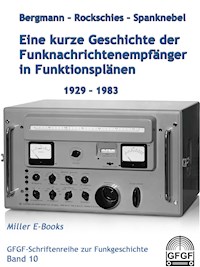


Table of Content
Prologue
1. The primeval - Tuned Radio Frequency Receiver
Knapsack receiver (“Tornister-Empfänger”) Torn.E.b. „Berta“, 1938
Lorenz Lo6K39, 1939
2. Classical period - superheterodyne receiver with frequency-variable first oscillator
Telefunken Spez. 281 Gr, 1929
Telefunken DF receiver E383N=EP2, 1933
Telefunken “Horchempfänger” Fu.H.E. 1, 1933
National HRO „Senior“, 1934
Hammarlund „Super Pro“ BC794, 1938
Board receiver Lorenz E10aK, 1939
Telefunken Fu.H.E.c, 1939
Medium wave receiver Mw.E.c „Cäsar“, 1939
Telefunken Kw.E.a „Anton“, 1940
Hallicrafters „Super Skyrider“ SX-28, 1941
Lorenz Ln21021 „Schwabenland“, 1942
Telefunken E52 „Köln“, 1943
Hammarlund „Super Pro“ SP600, 1948
National HRO-60, 1952
Lorenz 6P203.A9, 1953
Telefunken E103Aw/4, 1953
Telefunken E127Kw/2, 1953
Siemens E303/305/306, 1953
Telefunken E127Kw/4, 1954
Siemens E309a, 1955
Hallicrafters SX100, 1955
Siemens E566/E310, 1957
Hammarlund HQ170, 1958
Hallicrafters SX122, 1964
Final remarks on Group 2
3. The Collins phenomenon - superheterodyne receiver with crystal-stabilised first oscillator
3.1 Tunable first IF
Collins 75A-1, 1946
Collins 75A-2, 1950
Telefunken E104 Kw/4, 1953
Collins 75A-4, 1955
Collins R390A, 1956
Collins 51J-4, 1957
Collins 51S-1, 1961
Drake 2-B, 1961
Sommerkamp FR100B, 1965
Yaesu FR-101, 1974
3.2 Wide band first IF
Collins 75S-1, 1958
Collins 75S-3B, 1963
Squires-Sanders SS-1R, 1963
Receiving path National NCX-5, 1965
Receiving path Heath SB-101, 1967
Receiving path Sommerkamp FT277, 1971
3.3 Contemporary criticism
4. Two problems are pending - The frequency processing with continuous VFO and the single-range super
Racal RA17, 1957
Siemens E311a, 1959
Rohde & Schwarz EK07, 1960
ITT Mackay Marine 3010-B, 1966
Rohde & Schwarz EK56, 1968
Racal RA-6217, 1968
Racal RA-1217, 1972
Telefunken E 863 KW/2, 1969
Receiving path Yaesu FT-901DM, 1978
Receiving path Yaesu FT-902DM, 1981
Receiving path Kenwood TS-830S, 1981
5. There should be an easier solution - The Premixer concept with a fixed first intermediate frequency
Receiving path Drake TR-3, 1963
Receiving path Drake TR-4, 1965
Receiving path Drake TR-4C, 1972
Drake R-4, 1965
Hallicrafters SX-146, 1966
Receiving path National NCX-500, 1968
Drake R-4C, released 1973, modified 1976
Receiving path Yaesu FT-101ZD, 1979
Receiving path Ten-Tec Omni B, 1979
Receiving path Ten-Tec 560 Corsair, 1982
6. DIGITALANALOG – Single-range super with frequency processing and continuous VFO
Receiving path Drake TR7, 1978
Drake R7, 1979
7. DIGITALDIGITAL – Single-range super with full synthesis for digital or quasi-continuous setting
ITT Mackay Marine 3021A, 1973
RFT EKD 315, 1974
Rohde & Schwarz EK 049, 1975
Receiving path Collins KWM-380, 1979
Measuring receiver Rohde & Schwarz ESH2, 1979
Rohde & Schwarz EK 070, 1980
Cubic HF-1030, 1981
Receiving path Kenwood TS-930S, 1982
Receiving path Icom IC-745, 1983
References and Sources
About the authors
Kurt Bergmann, DL9WW
Joachim Rockschies, DL6CX
Heinrich Spanknebel, DC6IB
About the association
The Gesellschaft der Freunde der Geschichte des Funkwesens (GFGF) e.V.
Historical radio technology has many aspects
GFGF Membership
What GFGF is providing
About the publishing house
Imprint
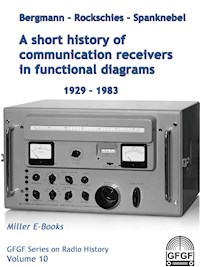
Bergmann –Rockschies –Spanknebel
A short history of
communication receivers in functional diagrams
1929-1983
GFGF Series on Radio History Volume 10
Prologue
This book gives an insight into the long technical development path of wireless receivers for commercial radio services as well as the amateur radio service over the period from 1929 to 1983, i.e. from the age of electron tube technology to the first assured phase of proof of semiconductor technology, by means of clear, partly simplified circuit and function diagrams.The authors have handled worldwide radio communications in the amateur radio service over three decades, thereby getting to know the often extreme requirements that those receivers should be able to cope with, and in parallel analysing more than 70 radio message receivers or receiver parts of transceivers.For those who collect such devices or would like to learn about their functioning, the functional diagrams compiled here provide the best possible assistance. The extensive bibliography and list of sources open numerous avenues for more in-depth study or for obtaining documentation.The GFGF has already published two editions of this reference book in 2001 and 2002, which have long been completely out of print. I have therefore now reissued it as an e-book in 2022 and translated it to English, so that it is now available indefinitely to both preservationists of old technology and new radio enthusiasts.
Wolf-Dieter Roth, GFGF, DL2MCD, Fall 2022
1. The primeval - Tuned Radio Frequency Receiver
A radio receiver normally has to fulfil the following basic tasks:
1) Selection and amplification of the incoming radio frequency signals from the receiving antenna.
2) Demodulation of the amplified high-frequency signal in order to recover the audio-frequency signals contained in the oscillation modulation. In the case of unmodulated telegraph signals, an auxiliary oscillation must be added to create interference.
3) Final amplification of the obtained audio frequency signals for output to headphones or loudspeakers.
4) At least manual, later also automatic gain control to avoid overmodulation and to ensure an optimal playback volume.
In Tuned Radio Frequency receivers (TRF), the selection of the desired reception signal is done by tunable resonant circuits. In the classical era considered here, the amplification was done by electron tubes. For demodulation, the so-called audion set-up of an electron tube was used in the standard case. If an auxiliary oscillation is required, the feedback can be set slightly supercritical so that the audion circuit changes to an oscillating state. To achieve the desired interference pitch, the audion tuning must be adjusted with appropriate sensitivity.
Knapsack receiver (“Tornister-Empfänger”) Torn.E.b. „Berta“, 1938
A 3 stage receiver with 4 valves RV2P800, Photos and circuits [2], [6], [7].
Vorselektion: Preselection
Tonsieb: Filter
NF-Stufe: AF stage
8 Bereiche: 8 ranges
Abstimmung: Tuning
Verstärkung: Amplification
Rückkopplung: Feedback
Lorenz Lo6K39, 1939
Very eleborate 6 stage receiver with 5 valves RV12P2000. [2], [8].
Vorselektion: Preselection
Tonsieb: Filter
NF-Stufe: AF stage
8 Bereiche: 8 ranges
Abstimmung: Tuning
Verstärkung: Amplification
Tonhöhe: Pitch
Rückkopplung: Feedback
Comment: The oscillating circuit sets to be tuned to the respective reception frequency cannot be optimised to a transmission bandwidth suitable for near selection and are very complex. In the typical state of development shown here, there is still no automatic gain control.
2. Classical period - superheterodyne receiver with frequency-variable first oscillator
The desire to be able to optimise the resonant circuit sets of a receiver for near selection led in 1913/1914 to the invention of the superheterodyne receiver [1, p. 47], abbreviated also superhet or even simply super.
In the superheterodyne receiver, an oscillator frequency generated in the receiver is mixed with the desired reception frequency in such a way that an intermediate frequency (IF) with a constant nominal value is produced as an interference product.
In the case of additive mixing, the sum of the received oscillation and the oscillator oscillation is fed to a control electrode with a curved control characteristic that changes in steepness, which leads, among other things, to the formation of a product between the two oscillations. In the case of multiplicative mixing, the two oscillations involved are fed to two separate control electrodes, which influence each other multiplicatively from the outset.
The multiplication of two sinusoidal oscillations of different frequencies leads to the formation of the sum frequency and the difference frequency according to a known addition theorem:
A receiver is then usually designed in such a way that the difference frequency created for a desired reception frequency corresponds to the intermediate frequency.
However, this creates the problem of image frequency reception: If, for example, the oscillator frequency is set higher by the IF than the desired reception frequency, an input signal that happens to be higher by twice the IF produces the same IF, so that selective separation is no longer possible. In addition, input signals randomly spaced apart by the IF can also generate IF signals at non-linear characteristics. Therefore, sufficient preselection must be ensured before the mixing stage of a heterodyne receiver.
Telefunken Spez. 281 Gr, 1929
Vorselektion: Preselection
ZF: IF
Begrenzer: Limiter
Regelung: AGC
Überlagerer: Oscillator
A large station receiver for transoceanic teletype operation [9] [10], at that time a pioneering achievement in radio development [11] [12] [13]. In order to obtain an image frequency suppression of the order of 104


