16,99 €
Mehr erfahren.
- Herausgeber: Crowood
- Kategorie: Lebensstil
- Sprache: Englisch
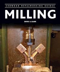
Milling is one of the principal and most versatile machining processes for sizing parts in the workshop. Whether a professional engineer looking for advice, or an amateur looking to install your first milling machine, this book will show you how to make full use of your milling machine safely and effectively, and enhance your milling skills. Focusing on the commonly used vertical mill and vertical turret mill, and with practical advice and diagrams throughout, the book includes: a guide to buying, installing and using a small milling machine and accessories; basic cutting tool principles and more advanced milling methods, including drilling, tapping and reaming; and instruction on a variety of techniques ranging from work holding in the vice to using a rotary table. Aimed at anyone with a workshop, and particularly home metalworkers, engineers and professionals, and fully illustrated with 167 colour illustrations and 45 diagrams.
Das E-Book können Sie in Legimi-Apps oder einer beliebigen App lesen, die das folgende Format unterstützen:
Seitenzahl: 203
Veröffentlichungsjahr: 2014
Ähnliche


First published in 2014 byThe Crowood Press LtdRamsbury, MarlboroughWiltshire SN8 2HR
www.crowood.com
This e-book first published in 2014
© The Crowood Press 2014
All rights reserved. No part of this publication may be reproduced or transmitted in any form or by any means, electronic or mechanical, including photocopy, recording, or any information storage and retrieval system, without permission in writing from the publishers.
British Library Cataloguing-in-Publication Data A catalogue record for this book is available from the British Library.
ISBN 978 1 84797 775 5
Frontispiece:
A Tom Senior light vertical milling machine suitable for use in a small workshop.
Acknowledgements
I would like to thank the following for the use of some of their illustrations: Arc Euro Trade, MyHobbyStore Ltd (Publishers of Model Engineer and Model Engineers’ Workshop), Warco and Ken Willson.
Contents
Introduction
1 The Milling Machine
2 Buying the Mill
3 Using the Mill Safely
4 Cutting Tool Principles
5 Setting Work True and Finding the Datum Position
6 Work Holding in the Vice
7 General Machining
8 Machining on the Table
9 Using a Rotary Table and Milling Radii
10 Using a Dividing Head
11 Drilling, Tapping and Reaming
12 Boring Holes and Repetition Work
Glossary
Further Information
Index
Introduction
This book will assist the reader in developing their milling skills and applying them to make finished pieces of work accurately and to very high standards. If you are an amateur or professional engineer who is perhaps looking to install your first milling machine in your own workshop, this book is for you. It is a complete comprehensive guide to buying, installing and using a small milling machine, with the accessories that you will need to use the milling machine to its full capabilities. The book will teach you milling from the basic principles right through to advanced milling methods. Whether you are working in a home or light industrial environment, you will learn the important milling skills and insider tips from someone who has spent a large part of his life milling in industry.
There are several types of milling machine such as CNC mills, horizontal mills, vertical mills and machining centres. The milling machine we will concentrate on is the vertical mill and the vertical turret mill, which are the ones that will be most likely to be found in the small workshop. Many of the principles of milling apply to the entire range of milling machines so this book will be useful to, say, the horizontal milling machine owner as well as the CNC milling machine owner. The milling machine is very versatile – at a pinch it can also be used as a simple lathe by holding the workpiece in the milling machine spindle and a lathe tool in the machine vice.
ABOUT THE AUTHOR
I spent more than thirty years in the engineering industry, mostly doing milling in all its forms. I was trained to make industrial sewing machine components which, as you can imagine, are mostly very small and were made to very tight tolerances. I also worked on the huge wing holding fixture used by Airbus to transport wings in their Supper Guppy aircraft. I have also trained many people in milling machine practice and engineering in general.
I was the editor of Model Engineer magazine for about five years and I edited Model Engineers’ Workshop from 2007 to 2014; these are the two main UK magazines for machining in the home workshop. This editing experience has given me a unique insight into what amateur engineers need to help them succeed. This book will enable you to get started with a milling machine in your workshop easily and, most importantly, safely.
Model Engineers’ Workshop magazine, first published in 1990, is a recent addition to the model engineering scene. It often covers projects and techniques suitable for the milling machine. A new issue goes on sale every four weeks.
The Model Engineer magazine is probably the world’s longest running model engineering hobby magazine and is published every fortnight. It is mainly about making precision models but often includes articles about milling machines. The milling machine depicted on the cover of the issue shown is a model of a horizontal milling machine made by Ray Griffin.
WHY DID I WRITE THIS BOOK?
I have worked with many engineers, both beginners and experts, and have taught many young people during their first steps into engineering. When I worked in the engineering industry, mainly on milling machines, I found ways to work quickly and accurately, very important when you were self-employed and did not get paid if you scrapped a job. I learnt a lot from many expert engineers and also by machining many different types of component. I would like to pass some of this knowledge on to you, the reader. When you have learnt all about milling, you may in turn teach someone, perhaps a grandchild, all they need to know about milling.
A milling machine is very useful and will contribute greatly to the success of a workshop. The lathe is often called the king of machine tools. I consider the milling machine to be a close second to the lathe but really, the milling machine is far more versatile than the lathe. In industry, most millers can do turning, but often the turners do not know how to mill. The same applies to CNC millers in industry; most CNC millers think they can mill but usually, unless they went through the manual milling training stage, the majority of CNC millers are just programmers who know how to program and set up a CNC milling machine but do not know the correct way to mill.
I will be concentrating on the vertical milling machine rather than the horizontal milling machine. Also, although this book is a complete introduction to milling, it does not cover CNC milling. If you wish to learn CNC milling, this book is still ideal for learning the basics of CNC milling as the basic principles are the same, but the programming side of CNC can be learnt from Dr Marcus Bowman’s book CNC Milling in the Workshop in the Crowood Metalworking Guides series of books. Marcus Bowman’s book is an ideal companion to this book if you are considering buying a CNC mill.
Dr Marcus Bowman’s book in the Crowood Metalworking Guides series is an excellent introduction to CNC milling.
WHAT YOU WILL LEARN FROM THIS BOOK
Following a brief history of the different types of milling machine and their uses, we will consider how to choose a milling machine depending on what you want to do with it. What is the largest size of work you are likely to want to machine? What speeds are required? What size of milling machine should you buy? What features are desirable?
Next we will discuss buying a milling machine. Should you buy new or secondhand? If you are thinking of buying a new milling machine, we take a look at some of the current types and makes. When buying second-hand, what should you look out for? Learn how to test a second-hand milling machine for problems. Find out the best way of transporting the milling machine home after the purchase, how to set up the milling machine and how to check for accuracy, as well as adjusting and maintaining the milling machine to get the best accuracy and performance.
Then we need to consider general safety on the mill, including milling machine guards and safe working practices, climb or down-cut milling and conventional or up-cut milling. From there we consider the various types of cutters used and cutting tool principles, including a useful chart showing the correct speeds and feeds for different materials, with a look at homemade cutter grinders.
The first important task we will explore is setting work true and finding the datum positions. Find out how the X, Y, and Z coordinates work, together with a guide to the wobbler/edge finder and the different types of edge finders used for slots, holes and datum edges. Learn how to edge find from the vice jaw and parallels and how to find the centre of round bars. Learn to use the digital readout to pitch out hole centres and mill components to size. Discover how to set work for accurate boring of holes using toolmaker’s buttons with parallels. Learn about the different types of dial test indicator including the lever indicator and the plunger indicator and how to use them to set work, machine vices and other fixtures accurately. You will also learn how to tram the milling machine’s head square, as it is essential for the milling machine’s head to be set square to ensure accurate work.
Then we turn to work holding in the vice, including the machine vice, the toolmaker’s vice and some other types of vice. Learn about clocking the vice parallel, clocking the jaw vertical and skimming soft jaws true. Find out how to use a nest to hold the work, methods of using a vice stop on the milling machine and how to mill squares and hexagons in the vice.
In our consideration of general machining on the mill, we discuss how to machine a square block in several different ways, machine a flat surface and machine a slot. Tasks covered include how to machine a keyway and how to make thin shims. We also take a comprehensive look at forming shapes with a ball-nose cutter, as well as making cylindrical squares, using 123 blocks, and angle plates. Finally, we cover several different methods of machining angular faces.
Then we discuss how to machine large components on the milling machine’s table, and how to use tenons, tee nuts, studs, clamps, parallels, packing blocks and vee blocks. You will learn how to set work square using the angle plate and the sine bar, and find out how to use the three-jaw chuck and the ER collet chuck attachment on the milling machine table.
We next look at using a rotary table, including centring the table and centring the work, machining radial slots and large internal radii and drilling radial holes, as well as various clamps, packing and the Keats vee angle plate.
This is followed by how to use a dividing head using both simple indexing and the division plates. You will learn how to line up the cutter with the centre of the dividing head, set up the dividing head parallel to the milling machine and parallel to the dividing head tailstock, and how to use a dividing head to produce a 13-hole circle including how to set up the division plates. You will learn to use your dividing head to cut a square and a hexagon; how to mill a dovetail using the dividing head and how to mill a gear wheel. Find out how to set the tilting dividing head and milling machine head for machining larger work than the machine’s cross travel will allow.
We will look at drilling, tapping and reaming holes and the many different drill types, considering taps and reamers of various types and how to select speeds and feeds. We will cover calculating hole positions when drilling holes on a PCD (pitch circle diameter) or angle, including a set of charts to calculate the positions of holes on a PCD. Finally we look at boring in the milling machine and repetition work, considering the different styles of boring bars and their methods of use and how to check a bore for accuracy.
Many people who wish to install and use a milling machine do not have a friend or local model engineering club member to help them in their first steps to becoming proficient with it. Even if you have no previous milling experience, while it is harder to learn milling on your own without anyone to help you, with this book you will quickly become proficient with a milling machine and will be able to produce first class work within a short time frame.
1 The Milling Machine
The machines we will be discussing in this book are the vertical milling machine and the vertical turret milling machine. The principles of milling are also applicable to the horizontal milling machine, and some horizontal milling machines can be fitted with a vertical head (when they are known as universal mills). Usually these are fixed heads and do not have a moving quill, however, so the only way to adjust the depth of cut is to raise and lower the mill’s table. Also available are slotting heads which bolt on in place of the vertical head, and the tool moves up and down rather than rotating.
The vertical milling machine is basically the same as a turret milling machine, but the turret milling machine is much more versatile. While both types of milling machine have their spindles in the vertical plane, the turret milling machine spindle can usually be tilted to the left or right and sometimes forwards and backwards. The plain vertical milling machine can usually only be tipped to the left and the right, often by tilting the whole vertical column that the head is mounted on.
A typical example of a turret milling machine is the Bridgeport style mill. This is quite a large machine, but many are finding their way into the home workshop. These mills are a standard item in many industrial workshops and are often available at a reasonable price. They do however require a specialist machinery transport company to move them as they are very heavy and are not really suitable for the amateur engineer to move by themselves.
Fig. 1.1 A typical bench mounting vertical milling machine as used in home workshops is the Warco WM 14 milling machine shown here. You can buy purpose-designed cabinet stands for most of the Warco range.
Fig. 1.2 The Warco WM 16 milling machine can also be supplied for bench mounting.
A typical vertical milling machine will be much smaller than the Bridgeport milling machine and can often be moved by two people, possibly assisted by an engine crane if it is a larger mill. It is usually possible to split the milling machine into two parts: the base unit complete with the machine’s table, and the column with the head and motor assembly combined. When you have lifted the base onto the bench or machine stand, you can then add the column and head.
Also available are much smaller turret mills than the Bridgeport, often called VMCs (vertical machining centres). On a turret milling machine the head can usually be twisted to the right and left and rotated around the column, but it cannot usually be tilted forwards and backwards.
Fig. 1.3 A Bridgeport milling machine can often be found in commercial factories, but more and more are finding their way into home workshops. They usually have a self-contained X axis power feed gearbox for moving the table under power feed.
Fig. 1.4. This Warco WM 16 milling machine, seen here on its purpose-made stand, is often found in the home workshop.
CHOOSING A MILL
Size
The first thing to decide is: what is the largest piece of work you will be milling on the machine, and what is the largest diameter you will want to hold in the dividing head.
It may be that the longest and widest item you will want to hold is a pair of locomotive mainframes. Perhaps the largest diameter is a traction engine rear wheel for drilling for the spokes and strakes and so on. The locomotive frames can be moved along the table so the table length and movement is not too critical. They can also be rotated 180 degrees to access the far side of the frame plates.
Fig. 1.5. A small turret milling machine will be found to be very useful in the small workshop. This example by Warco is typical of this type of machine. It is quite easy to fit a digital readout, a power feed attachment and a machine light to improve on the machine’s facilities.
A Bridgeport milling machine will usually have an X axis travel of 26in (660mm) and a Y axis travel of 12in (300mm) although I think this may vary slightly on some models. This will be sufficient for all but the largest models.
A typical medium-size, hobby-type milling machine will have an X axis travel of about 19in (485mm) and a Y axis travel of 7in (175mm). A small milling machine will have an X axis travel of about 13in (330mm) and a Y axis travel of 5.5in (145mm). These dimensions will vary with different manufacturers and should be considered a starting point only.
When mounted in the dividing head, the traction engine wheel can be almost twice the diameter of the Y axis movement, as the wheel rim can be rotated so that every part of the wheel can be beneath the centre of the milling machine spindle.
You will also be able to do larger work on a turret milling machine than on the vertical milling machine, as often the milling head can be moved in and out on the machine’s ram. (The ram is a large dovetailed slide on the top of the milling machine’s column that allows the milling machine’s head to move in and out and often to rotate.) In this case, you leave the work in the same position on the table and re-datum the work after moving the head on the ram. Often, the ram can pivot to the left and to the right to access all areas of the workpiece. If you are machining a large traction engine wheel rim on a turret milling machine where the head can swivel to the side, you can place the wheel on the table so that the table is in the centre and completely surrounded by the wheel.
Speed
The speeds required for milling will depend on the work you are doing, but unless you are doing very fine work such as engraving, a maximum speed of about 2,000rpm will be more than sufficient. A lot of the modern small mills will have an electronic speed control, sometimes combined with a high/ low gearbox. A Bridgeport milling machine will often have a two-speed motor as well as back gear to reduce the speed. Another type of Bridgeport head has a variable speed which is altered by turning a hand wheel.
Fig. 1.6. You can use a rotary table to drill a traction engine wheel for the spoke holes. Depending on how you position the rotary table and the milling table you can drill holes at a large radius on a modest size mill. This illustration shows the spoke hole set at 45 degrees from the centre of the table. The machine’s spindle is static; only the rotary table and the wheel rim will rotate to drill further holes. You will have to use some extension bars to clamp the traction engine rim to the rotary table.
Fig. 1.7. You can use a dividing head to drill a traction engine wheel for the spoke holes. If you tilt the milling machine head at 45 degrees and the dividing head at 45 degrees you can mill and drill quite large diameters even on a smallish mill.
MILLING MACHINE ELECTRICS
With single-phase electrics you plug the mains lead from the milling machine straight into the mains supply in your house or workshop. The motor is fed from the live, neutral and earth leads. Mills built for industrial use almost always have three-phase motors. Three-phase motors need three live wires. Each wire will be on a different phase. Each phase is like an incoming wave on the seashore, with three waves, one after the other, making up the three phases required. Each phase is the same voltage and current as the preceding one, but each phase takes up a third of each cycle so three sequential phases add up to each complete cycle.
A Bridgeport turret milling machine will almost certainly have three-phase electrics and, unless you are lucky enough to have a three-phase supply to your workshop, it will require a single to three phase converter.
Some three-phase motors will run from a single-phase supply via a converter or an inverter. To install a converter or inverter the converter/inverter maker’s instructions should be followed.
Inverters
Some change-over tags may be fitted inside a motor to change it from 440V three-phase down to 240V three-phase. In this case, the motor information plate will often say 240V/440V. If the motor plate says this, the motor is almost certainly capable of running on an inverter; it is just a matter of changing over a few connections inside the motor. This is usually an easy job involving moving some brass or copper links from one terminal to another. Instructions are usually on, or inside, the motor’s cover. The three-phase inverter or converter setup will give a quieter and smoother running motor compared to a motor running on a single-phase supply. The inverter will need a little bit of programming to set it up, but if you follow the manufacturer’s instructions it will only be a five-minute job to get the motor and inverter combination working properly.
Although the inverter runs at a constant voltage the frequency can be varied. This variation changes the motor speed as the inverter frequency is raised or lowered. I would limit the inverter speed variation from half speed up to full speed so that the motor is still cooled by the fan and does not overheat. You can change the main speed steps using the belts as you normally would. (If you wanted more speed variation, you could fit a separate computer cooling fan to give increased airflow through the motor to keep the temperature of the motor within its limit.)
Fig. 1.8. On a Bridgeport mill, the ram can be moved right in to work on one side of the work.
Fig. 1.9. The ram can also be moved out to work on larger workpieces.
Converters
The two main types of converter are the rotary converter and the static converter. The rotary converter will run more than one motor at a time, while the static converter is only designed to run one motor at a time. If you want to run two or more machines at the same time or perhaps run two motors on one machine, perhaps the main machine motor and a motor for the machine’s coolant pump or power feed system, then go for the rotary converter.
Rotary converters cost three to four times more than an inverter depending on the size and power output required. If you are running one machine at a time, buy the slightly cheaper static converter. If you fit the static converter with a three-phase socket connector, you can plug in your different machines one at a time. This will suit many home workshop users because for safety reasons you should only run one machine at a time.
SAFETY REGULATIONS
There are several manufacturers in the UK who supply converters and inverters. Make sure you get one that is CE marked and complies to the EMC regulations, the low voltage directive and BS EN ISO 61000-3-2: 2006.
To reverse a three-phase machine if it is running in the wrong direction, just change over any two of the phases by reversing any two of the power wires.
CONVERTER RATING
Rotary and static converters must not exceed their maximum rating. If you are not sure of the load capacity limits required to power your machine(s) the converter manufacturer or supplier should be able to help you.
Fig. 1.10. You can also swivel the ram round to the left or right to get at large workpieces.
Fig. 1.11. If you have a particularly large rim to drill or machine, you can swivel the machine’s head and ram away from the knee of the machine and put the rim over the surrounding table. You will have to use a location fixture, possibly locating from the previously drilled spoke holes, to drill the strake holes. It takes a bit of figuring out but it can be done. I had a rim about 2ft diameter for a packaging machine which required about 42 tapered slots milled in it, and after a lot of thought this was the method I came up with to do it. It worked perfectly well.
OTHER FEATURES
A digital readout is often seen as an extra add-on to a milling machine, but I consider it an essential feature. Whether you use a simple scale system similar to a digital vernier scale or a full readout with glass or magnetic scales, you should always buy a machine with a readout fitted or fit a digital readout to your mill. You will never regret it (simple instructions for fitting a digital readout to a milling machine are given in Chapter 2


