20,99 €
Mehr erfahren.
- Herausgeber: Crowood
- Kategorie: Lebensstil
- Sprache: Englisch
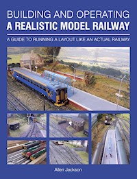
This informative book provides a step-by-step account of the construction, from scratch, of a model railway called Dovedale. The model is operated like a real modern railway and was built entirely by the author within a strict low budget, using, wherever possible, recycled materials. Moreover, Dovedale is based on a specific prototype that exists in Buxton in Derbyshire, where freight trains run into an interchange siding, the locomotive runs round the train and then departs to a different destination. Some model railways are operated somewhat chaotically and are characterized by frequent derailments and locomotives that stop arbitrarily. If you wish to move away from this kind of layout and construct a model railway that operates realistically and reflects more closely the way that railways actually work in the second decade of the 21st century, then this is the book for you. Whilst constantly emphasizing realistic operation, the book covers layout planning and construction, controllers, point motors, power supply, cables and connectors, ways of operating traffic flows, signalling, track droppers, control panels and wiring, control and interlocking, lighting, sequence and block bells, the use of closed circuit television, and much more.
Das E-Book können Sie in Legimi-Apps oder einer beliebigen App lesen, die das folgende Format unterstützen:
Veröffentlichungsjahr: 2016
Ähnliche


BUILDING AND OPERATING
A REALISTIC MODEL RAILWAY
A GUIDE TO RUNNING A LAYOUT LIKE AN ACTUAL RAILWAY
Allen Jackson
THE CROWOOD PRESS
First published in 2016 by
The Crowood Press Ltd
Ramsbury, Marlborough
Wiltshire SN8 2HR
www.crowood.com
This e-book first published in 2016
© Allen Jackson 2016
All rights reserved. No part of this publication may be reproduced or transmitted in any form or by any means, electronic or mechanical, including photocopy, recording, or any information storage and retrieval system, without permission in writing from the publishers.
British Library Cataloguing-in-Publication Data
A catalogue record for this book is available from the British Library.
ISBN 978 1 78500 170 3
Disclaimer
The author and the publisher do not accept any responsibility in any manner whatsoever for any error or omission, or any loss, damage, injury, adverse outcome, or liability of any kind incurred as a result of the use of any of the information contained in this book, or reliance upon it. If in doubt about any aspect of railway modelling readers are advised to seek professional advice.
Frontispiece
Fig. 1 Northern Rail class 153 is about to depart from Platform 2 at Dovedale station and take the left-hand branch at the tunnel mouth to Buxton. The two semaphore signals indicate the points are correctly set, as they are interlocked, and the colour light indicates that track power is selected to the Dovedale operator so that the train can be driven straight into the fiddle yard.
Dedication
For Ninette.
Acknowledgements
To signallers and other railway staff who have been kind enough to share their interest and experiences with me.
Author’s note
I have tried to make this book eminently practical as well as perhaps readable. Not only that, there is some idea of what it will cost if you decide to build something yourself; these prices were accurate at the time of writing (September 2015).
CONTENTS
INTRODUCTION
CHAPTER 1 LAYOUT PLANNING
CHAPTER 2 LAYOUT CONSTRUCTION
CHAPTER 3 CONTROLLERS AND CONTROL
CHAPTER 4 WAY OF OPERATING AND TRAFFIC FLOWS
CHAPTER 5 ELEMENTS OF INTEGRATION
CHAPTER 6 SEQUENCE AND BLOCK BELLS
CHAPTER 7 CLOSED-CIRCUIT TELEVISION (CCTV)
CHAPTER 8 DOVEDALE SUMMARY
APPENDIX I LAYOUT COSTINGS
APPENDIX II OPERATIONAL SEQUENCE
INDEX
INTRODUCTION
The initial thrill of operating a new train-set eventually fades and perhaps you get round to thinking ‘Is this all there is?’; and whilst a train set provides the basics of a train that moves, there are so many aspects to real railway operation that provide a fascinating and satisfying continuation of the hobby to provide an enduring appeal.
The emphasis on prototype railway operation has built up over the years to be one of control and safety. In the early days, some horrific accidents gradually changed the operating ethos from one that involved elements of chance, where passengers’ lives took a turn on the roulette wheel, to a network based on efficiency and safety.
The media are never slow to tell us of overcrowding and delays due to over-running engineering works but the railway is suffering growing pains again after fifty years of being rundown and neglected. Real substantial efforts are being made at all levels to build and run railways that the nation can be proud of. You only have to look at the recent television documentaries about First Great Western and East Coast Trains, where the staff have contracted that peculiarly un-British condition of unswerving customer service, to realize the sea change that has been going on. Let’s hope it’s highly infectious.
You may take it from this that the book will be about a model railway that is bang up to date and reflects Network Rail and the train-operating companies as they were when this book was written in 2015. That said, the railways are a mixture of the most modern and Victorian infrastructures side by side, and therein lies a part of the fascination with the current railway scene. It is a scene that is rapidly changing and a way of life that is disappearing.
Also, to have written a book about building a model railway in the steam age would probably not appeal to those setting off on model railway building as, preserved railways apart, it is now so long ago as to be beyond the memory or experience of all but bus-pass holders.
The building of a model railway is something that requires an holistic approach or one that involves the whole process to achieve realism. Early on in the planning for this book it was decided to build a model railway layout from scratch specifically in support of the book, and to invite the readers along for the ride and even have a go. In this mostly post-industrial society fewer people are constructing or making things for themselves in their work and yet the feeling abroad is that many would like to do so as a hobby. This book assumes little prior knowledge other than that you may know one end of a screwdriver from the other, but not necessarily what kind of a screwdriver it is.
The building of a model railway layout needs many skills and a few might include: woodworking, technical drawing, electrician, civil engineering, model craft, metalworking and painter. It is highly unlikely that everyone embarking on this project will have all the skills, but they can all be acquired to the degree necessary; the one quality needed is persistence. The nature of this particular beast is that folk will be doing stuff they haven’t done before and that is always a little daunting, but persistence always pays off. You will get there eventually. There are always dodges and shortcuts that can be employed as a substitute for skill in a particular department, and the book makes full use of them.
Costs are seemingly an unanswered question in books like this and it may be the one thing that can put people off if they don’t know how much to budget for. The layout as built is fully costed – except where it comes down to rolling stock, which is very personal and depends on whether it was bought new or second-hand. In any case, this is one area where Google can assist with the information. The costs will be for the layout built and that will not apply directly to everyone, but a ball-park figure will be arrived at and clearly the costs can be incurred over time as the layout is built.
Also not directly costed in are tools, as these costs would be amortized or spread out over the life of such items, which should be years, but some indications of costs of tools appear.
A mixture of imperial and metric units appear in the book as that commonly reflects society as it currently is but, where appropriate, the other equivalent of the units used will be quoted.
Fig. 2 Freightliner class 66 has run round its train of limestone wagons and is now signalled for Buxton and Manchester.
CHAPTER ONE
LAYOUT PLANNING
SCALE AND GAUGE
The railway featured in this book was built to OO gauge – rolling stock for which is in 4mm to the foot scale – and it might be helpful to define the difference between what we mean by scale and by gauge as this will help us make an early planning decision.
Scale is the ratio of the model to the real thing and can be expressed as, for example:
1:76 scale – in other words, the model is 1⁄76 th the size of the real thing.
This value is often quoted on model road vehicles and buildings to let us know they would be suitable for the layout.
OO gauge refers to the distance between the rails of the model. There is no such thing as OO scale.
Fig. 3 Schematic diagram of track gauges and rail heights in OO gauge.
The top part of the not-to-scale diagram (Fig. 3) shows an end-on view of a piece of track and the track gauge of 16.5mm, which is OO gauge. Using our 4mm to the foot scale, we can see that the track gauge of 16.5mm divided by 4mm is equal to a track gauge of 4ft 6in in real life, which is too narrow for an absolute scale model.
The standard gauge in Britain and 60 per cent of the rest of the world is 4ft 8½in or 1,435mm. It is sometimes called the Stephenson Gauge after George Stephenson, a railway pioneer.
HO gauge –which also has a 16.5mm track gauge – is 3.5mm to the foot and so the outline of the rolling stock would be smaller if British outline rolling stock were used, but it is mainly found on the European continental scene. The European loading gauge or size of rolling stock allowed to go through tunnels and bridges is considerably larger than in Britain. The Channel Tunnel accommodates the larger continental rolling stock, as well as special vehicles to carry trucks and cars, but Eurostar trains conform to the smaller British loading gauge.
There is an organization called the EM Gauge Society (where EM means Eighteen Millimetres) who model to a track gauge of 18.2mm, and there is even the Protofour or P4 Association who model to an absolute track gauge of 18.83mm. These two, plus OO gauge modellers, all still model to 4mm to the foot scale.
The trouble is that none of the locomotives or rolling stock you can buy in the shops will run on the broader gauges, and to convert your favourite class 66 to run on EM, for example, would need specialist wheel sets from Ultrascale, adding over £50 to the cost of the one locomotive.
There is a dodge whereby the track gauge can look tolerably close to scale standards and a lot better than the usual but still use track you can buy in the shops and trains likewise. This has to do with an early planning decision that was taken for this book – the layout was to be a secondary line not the East or West Coast Main Lines. Most bedrooms or other domestic accommodation will not be suited to modelling the iconic quadruple track main line from Euston to Watford, for example.
Fig. 4 Comparison of flat-bottomed and bull-head rail heights, Thetford, Norfolk.
Figure 4 shows the main line and siding at Thetford in Norfolk. The main line is modern-ish flat-bottomed rail, soon to be replaced, and the siding bull-head rail. The difference in rail height shows up well here.
Flat-bottomed rail was introduced as a more stable rail capable of taking heavier loads at higher speeds, and per unit length it weighs considerably more than bull head. The other advantage of flat-bottomed is that it can use metal clips to attach the rail to the sleepers instead of chairs and wooden blocks or steel springs, which have to be hand-assembled with bull-head railed track. Flat-bottom railed track can be factory made in sections.
However, because of cost and the sheer scale of the task, many secondary lines continue to use bullhead rail where speeds, in particular with freight trains, on secondary lines are not high.
Back to Fig. 3 and it can be seen that the track gauge of the lower, bull-head rail piece of track appears to be of wider gauge, although it is identical to the top section of track.
Choosing code 75 railed track on a secondary lined model of a prototype is fine on both counts of scale appearance and fidelity to the prototype. Code 75 it is then. Any type of rail can have its appearance improved by painting the rails rust coloured, which they nearly all are in real life, and this too has the visual effect of lowering the rail height and thereby making the track gauge look true to the prototype gauge. Code 100 rail was originally used by model railway manufacturers, as they were using wheels with large flanges, known as coarse scale. The rail needed to be higher up to avoid the flanges hitting the sleepers. There are no popular manufacturers of locomotives and rolling stock in 4mm scale that use coarse scale any longer.
Some rails on the prototype are painted white, which, in the context of track gauge perception, makes the rails look taller and the track gauge narrower.
Fig. 5 White-painted rail at March South Junction crossing, Cambridgeshire.
Figure 5 amply illustrates the point and was taken in April 2015 at March South Junction in Cambridgeshire. The rails are painted white here because the track under the crossing is considered to be under additional stress to plain track. This stress, plus the heat of a sunny day, can cause cracks in the rail with potentially fatal consequences. Painting the rails white lowers the surface temperature by up to 2ºC (3.6ºF). Even this early in the year, the track gang was out measuring the rail temperature and they told me that the temperature was 31ºC (87.8ºF). The temperature limit before Network Rail start reducing the speed of the trains is 33ºC (91.4ºF).
LAYOUT TYPE
There are basically two types of layout in popular use and they are continuous run and end to end.
With the exception of the Circle Line on the London Underground, and the Docklands Light Railway, all railways run from point A to B and then possibly C and branch off for D and so on.
The concept of the end-to-end layout is of a train carrying out a journey and, although most of us are constrained by money and space to only model the last part of a journey, the continuous run nearly always takes up a good deal more room and does not operate like a real railway.
These thoughts are constrained by the desire to run trains as the prototype runs them. If all you want is a test track to run trains round there is nothing wrong in that but that is not what this book is about.
In other words, this book is about building a model of a prototype railway, insofar as that is possible within space constraints. Although the location will be imaginary, there have to be enough prototypical features to make the railway a believable, real location, and the way it works has to reflect what is done on the real thing. I say the location is imaginary and that is because it is virtually impossible to model to scale any prototype exactly – they are just too big. The largest size of layout that would fit the space I have available is 12ft by 2ft (3.66m by 0.61m). This means two boards of 6ft by 2ft (1.83m by 0.61m). As this is the most convenient and economical size for wood to be purchased, and also as what leaves the fiddle yard will be the same length as what arrives at the station. It will mean that the station and fiddle yard, or the part of the layout that represents the rest of the railway system, will be accommodated on one board each, pretty much.
PROTOTYPE SCENARIO
A specific prototype that would fit the model exists at Buxton in Derbyshire and it consists of two freight lines that meet in a junction. Freight trains run into an interchange siding, the locomotive runs round and the train then departs to a different destination that is in parallel with the original.
Fig. 6 Class 66, 66 020 and mineral train arrives off the single line from Brigg’s Sidings, Derbyshire.
Figure 6 explains this a little better. The class 66 and mineral train have emerged from private sidings, which are a branch off the main line. The train is about to take the crossover in the foreground and this leads to a long loop. The loco then runs round its train and then departs, taking the tracks we can see to the left of the signal box. These tracks lead to the rest of the rail system at Chinley Junction. The snow will not be modelled. This could mean two tracks from the fiddle yard leading to a loop line and siding for cripple wagons and possibly a locomotive stabling point. The tracks in Fig. 6 past the signal box to the extreme right of the picture lead to Buxton Station, so it is proposed to run Northern Rail DMU trains into a simplified station platform from the fiddle yard. There are actually very few places in the country where shunting and running round of freight trains takes place in Britain, and Derbyshire, centred around Peak Forest, Great Rocks Junction and Buxton, is one of the few and the busiest.
Fig. 7 Peak Forest South looking towards Great Rocks Junction, Derbyshire.
Figure 7 is at Peak Forest South with class 66 on the left shunting a train of limestone wagons, class 60 in the sidings with crippled wagons and a further class 66 on the right at the DB Schenker locomotive stabling point. The depot looks as though it carries out basic inspections and refuelling. The freight trains from Buxton, referred to in Fig. 6, arrive here travelling towards the camera. From the single-track branch at Buxton the line now has double running tracks, which are to the left of the signal box. The arrangement of the tracks is like the roads in Britain where the railways also ‘drive on the left’, so to speak. Most continental railways ‘drive on the right’ as per their roads. The semaphore signalling reflects this and the signals are usually placed to the left of the track they refer to, but this can change. Of paramount importance is the early view the driver gets of any signal and to this end signals are placed where they can be seen the best.
Clearly this could not all be modelled in the space we have but some of the flavour can be captured.
TRACK LAYOUT DIAGRAM
Fig. 8 Initial layout track diagram and arrangement of baseboards.
The not-to-scale schematic diagram at Fig. 8 is an initial view of what the facilities would be before the layout is built and before accurate sizing on the actual boards has taken place.
In every project engineering department, one activity invariably taking place is the production of ‘as built’ drawings. In other words, things can change and the finished product may vary from the initial design for all sorts of reasons.
Some design notes on the diagram:
Starting at the baseboard join and travelling to the left is a scissors’ crossover, which enables either of the two single-track lines coming out of the fiddle yard to access either the freight or passenger facilities. This represents the two single lines we saw at Buxton in Fig. 6 but they have both been enabled to carry passenger trains, which neither of the Buxton branches do, although passenger trains do access a station nearby but not via the branches.
This is a ‘scissors crossover’, which consists of four points and a diamond crossing, but in the model will be a double-slip, basically the same facilities but compressed to save space and, in addition, it only needs two point motors instead of four.
Fig. 9 Double-slip pictured between the LaFarge wagons at Earl’s Sidings, Derbyshire.
In Fig. 9, the double-slip is the piece of track with four tracks leading into it between the two sets of Lafarge wagons. It acts as a scissors’ crossover but is only used in slow-speed areas like station approaches and such like.
The freight tracks lead off to the bottom left-hand corner of the diagram, nearest the station controls, and it is here that most uncoupling will need to be done and so it is closest to the operator. The passenger facilities, on the other hand, shouldn’t need uncoupling facilities at all and can be kept at the opposite side to the operator.
The freight roads are canted at an angle and this is to accommodate the maximum length of train possible.
The fiddle yard uses a traverser – a sliding bridge on rails used to transfer locos and rolling stock between tracks without the need for points (seehttp://wikimapia.org/18765725/Traverser). This allows the maximum train length possible in the baseboard length we have. If points were to be employed, most of the space would be taken up by the points themselves and the resultant sidings would be woefully inadequate as regards wagon capacity. The 1ft or 305mm run in and run off to the traverser allows locos to run round trains and there can be a multitude of other sidings in parallel to the run off and run on traverser roads. The traverser is 4ft long (1,220mm) and this compares very well with the reception siding length.
Each traverser road has a push-button dead section at the end, which enables a train to be run from the station area and to come to an automatic halt, handy if operating on your own.
The traverser road furthest away from the fiddle yard operator is reserved for DMU traffic, once again because of the no-coupling requirement. The next road would be a run round to enable locomotives to head up trains. The other four roads nearest the fiddle yard operator are for freight traffic. This will get mixed up in the hurly burly of operating but these are what is required.
DISCLAIMER
In the construction phases that follow some companies are named and their products put forward and this is purely as a result of experiences with such outfits in the past. There is no commercial link between any such company and the author or publisher.
TRACK MANUFACTURERS
The decision has been made to go with code 75 rail, as that will give the most prototypical appearance for the type of line being built. There are several track options and perhaps an overview of them will not come amiss.
SMP (Scale Model Products) – Marcway – is based on the purchase of single rails to which is soldered cut-up, printed circuit-board strips for sleepers. A jig has to be manufactured and curved track has to be constructed in situ, as the finished item is rigid. The only way to undo this is to unsolder. After the track has been assembled, it has to be cut to ensure there are no short-circuits. Then the track has to be cleaned off from the soldering process, primed and sprayed with sleeper colour black/brown. Then the rails need to be painted rusty brown and the surfaces wiped off. The track is then ready to lay. It is highly realistic, runs well, is easy to make adjustments and much cheaper than factory-made track, but large amounts of work are needed to make the jigs and then the track, so this may not be suitable if you are just starting out.
C&L Finescale is a similar concept to above except that chairs are glued to sleepers and rails affixed to chairs. Great care is needed and there is much work required to get the track to operate reliably. Plywood sleepers have holes drilled in them to which is attached a copper or similar rivet. The rail is soldered to the rivet using track gauges and cosmetic chairs, and detail is glued on afterwards. It looks the business but it is highly labour-intensive.
Peco Streamline needs the minimum of effort to get it to work and with some subtle modifications can look quite realistic.
The decision was made to go for Peco Streamline as it was felt that newcomers would be more comfortable with the choice and be able to cope and see something for their efforts in a reasonable timescale.
EXHIBITION MATTERS OR PORTABILITY
It may seem premature to involve this in our planning but this is one area that needs to be addressed at this stage because, if you do decide to exhibit the layout, retrospective action to make it portable will involve much more work than if it is catered for now.
The largest single issue is that the baseboards can be divided into two, as they most certainly will not be going anywhere if they remain in 12ft by 2ft (3.66m by 0.61m) format. There are other issues, such as moving home or if you sell the layout, so it will need to be portable.
It may also seem odd that this is being discussed about what may be your first layout but if the smell of the crowd and the roar of the greasepaint appeals to you there is no barrier. The main thing is that, apart from the railway looking presentable, it must operate properly and to a recognized sequence that ensures that something is moving all the time. This is not easy on an end-to-end layout but will endear you to exhibition managers and the paying public. There are so many exhibition layouts that either don’t work properly or there is no organization to a sequence, and so movement is restricted to spasmodic events, where the public gets fed up waiting for something to happen and wanders off. Continuous run layouts are not immune from this condition either and have less of an excuse.
Writing a sequence for this model railway is one of the chapters and a sequence adds immeasurably to the fun you get operating the layout because this is what real railways do, only they call it a working timetable.
If the baseboards divide, then so must the wiring, and multi-way plugs and sockets will need to be plumbed in between boards and control panels. In addition, you may wish to insert another board at some point, and so the boards must be divisible from that standpoint.
There are many other issues yet to be addressed, such as signalling, ways of working and other prototypical features, which will form some of the succeeding chapters of the book. For now though, there is enough planning done to start work building it.
PROJECT MANAGEMENT
This layout building is undoubtedly a project and it needs management. We have all seen projects where possibly the management input was insufficient – Wembley Stadium, Millennium Bridge, Edinburgh Tram system and so forth. With anything that has Millennium in the title, clearly an end date is crucial, and we are all grateful the 2012 Olympics happened in 2012!
With a hobby, time and date are not as crucial, unless you are building to an exhibition deadline. Costs are the main issue here and so some monitoring and control of costs will ensure that the layout remains affordable. A summary of layout costs will be found in Appendix I.
CHAPTER TWO
LAYOUT CONSTRUCTION
BASEBOARD CONSTRUCTION
There are to be two 6ft (1,420mm) by 2ft (610mm) baseboards and as there is a high degree of track present, a solid baseboard top was chosen.
Another option is where a branch line runs through countryside in, say, a cutting, when it can be advantageous to lay a track bed and then surround the track bed with formers to make construction of the cutting easier and more realistic.
As to materials, the current vogue is 75mm by 25mm (3 by 1in) planed timber made into a frame and topped with 9mm ply for the track and scenery surface. This costs about three times as much as the solution chosen here and delivers no tangible benefits. If, after railway use, you require the baseboards to be a model of a World War II Vosper Thorneycroft RAF Air Sea Rescue Launch or possibly a Pathfinder RAF Mosquito, then go with plywood, otherwise save your money. The main requirement is that a baseboard must be capable of taking and holding a small woodscrew.
All of the initial baseboard material was purchased from B&Q and whilst they are not the cheapest for everything, they are nationwide and so someone reading this in Inverness, Pembroke Dock, Ballymena, Chichester or Lowestoft, or anywhere in between, could acquire these items. Also, if you buy too much of any one item, they take it back provided it is as bought. However, there will be some screws left over from the 1,000 in the box but they are not returnable.
Fig. 10 Basic baseboard materials.
Figure 10 shows the shopping list above, as bought. The rough-sawn timber can be smoothed down with sandpaper but most of it will remain covered up and so this is not necessary. The layout sides will be finished off with hardboard and so most of the rough-sawn timber will be obscured from view.
Fig. 11 The basic tools used to construct the baseboards.
Figure 11 has the basic tools needed to start the process and others will be needed as work progresses. The grey mains-powered item is a mitre saw, which is needed to cut pieces of the 1,800mm rough-sawn timber accurately and at right angles to length to form the framework. The alternative is to use a set square to accurately mark out the timber and saw around the mark. If your sawing is not that accurate, it will show. The mitre saw was about £20 and is the ‘cheapo’ version, but we are not cabinet-makers to the Royal Court of Louis XIV or any other mark of Louis come to that – it will do the job. The drill bit in the power drill is 3mm in size and will be used to drill a pilot hole to guide the screws in. The screwdriver bit in the smaller power drill is a posidrive, cross-pointed or Phillips-type bit.
Material Costs: Baseboard Construction
Item Description
Quantity
Cost each – 2015
Sub-Total
1,828 × 610 × 12mm Chipboard
2
£11.08
£22.16
1,800 × 38 × 25mm rough-sawn timber
Pack of 8 timbers ×3
£8.00
£24.00
Drywall 40mm countersunk Philips head screws
Pack of 1,000 in 1 box
£7.00
£7.00
Total Cost
£53.16
STATION BASEBOARD
Fig. 12 Overview diagram of the construction of the station baseboard.
The not-to-scale diagram at Fig. 12 shows exactly how the main 72in (1,828mm) rough-sawn timbers form nearly all the length of a long side and another piece of the rough-sawn timber makes up that long side. In other words, we only need one saw cut to do three sides of the frame. The rest of the frame is made up by cutting five pieces of rough-sawn timber to the dimensions shown.
The 2ft or (610mm) of the long lengths of rough sawn timber can be marked for cutting by placing against the edge of the chipboard and marking with a felt-tip pen and then cutting with the mitre saw. Make sure that the blade of the mitre saw is right on the line by lowering the blade first with no power on. Then, fingers out of the way, make the cut. I say this because a saw cut will be of a certain width and may affect the length of cut if you are not careful. There may have to be a few pieces of wood expended in the quest for satisfactory results but this is quite normal when you are starting off.
So we now have the five pieces of 22in (559mm), one piece of 24in (610mm) and the two as bought 72in (1,828mm) plus a chipboard sheet. Before we can assemble the frame to the chipboard, we need to mark out the chipboard so that we have a good idea that the screws will be going into the frame timbers.
Fig. 13 Marking out a chipboard sheet ready to have the frame screwed to it.
Use a piece of the rough-sawn timber as a guide to mark out the chipboard prior to drilling and affixing the frame (Fig. 13). The chipboard will rest on the narrow 1in (25mm) edge of the rough-sawn timber, so use this edge down on the chipboard to mark out the edge within which the screws must be if they are to go through the chipboard and into the rough-sawn timber frame.
Fig. 14 A baseboard has its frame secured to the rough-sawn timbers and the screws countersunk.
After the pilot hole has been drilled more or less in the middle of the marked-out line, we can countersink or recess the hole to take the screw head (Fig. 14). This is vital for the smooth running of the trains, as some of the track will be laid across the top of the screw heads and, therefore, there must be no suggestion of a screwhead protruding above the surface. The countersink tool is shown fitted to a manual handbrace, as all you need is a few turns to make the recess.
Should you get fed-up with this after a while, the electric screwdriver with the Phillips screwdriver bit makes an admirable countersinker with just a quick burst. You could only really do this with chipboard and certainly not with any metal.
One thing to note, when you are putting in screws in the rough-sawn timber ends, as opposed to the chipboard, remember that the two pieces of rough sawn are only 24mm thick in total and therefore need a shallower pilot hole, say 15mm.
Fig. 15 Showing the use of a square to mark off the place where pilot holes will be drilled on the chipboard to attach the framing.
The intermediate 22in (559mm) bracing struts are now fitted. Mark the rough-sawn timber edge pieces along their length at 12in (305mm) intervals and position the crosspieces as shown in Fig. 15. They should be a tap-into-place fit. Mark up using a square, as shown, with a felt-tip pen on both sides of the board. Join the two sets of mark-ups such that you have a crosswise pair of lines within which you can drill pilot holes that will take screws to go through and hold the chipboard to the cross-strut.
Fig. 16 The purpose of the marking out in Fig. 15 is clearer, as the supporting piece of rough-sawn timber cannot be seen but we still need to secure it to chipboard.
Figure 16 shows the intended effect of the previous procedure and demonstrates that the line drawing and so forth were necessary, as you cannot see the cross-struts underneath.
Note how the line of screws stops short of the ends, as this is where the side pieces are screwed into the cross-struts and we would not wish the two to collide. Note how smooth and well-finished the timber is – why pay more?
It does not require the centre of the line to be marked out, that is just a guess but works fine. There is no prescription as to how many screws will be needed but as the box contains 1,000, we can be generous and there will still be plenty left for future work.
Before the station board is finished, the next job is to prepare one end to connect to the fiddle yard board. First of all cut another piece of 24in (610mm) rough-sawn timber; this is to be the piece of the fiddle yard board frame that marries up to the now existing station board. Mark out the place where this is to be drilled – 6in (150mm) from the ends and in the centre of the 38mm-wide piece of rough-sawn timber.
Fig. 17 The piece of end framing for the next board is clamped to the now built baseboard.
As shown in Fig. 17, clamp the piece just marked out to the end of the station board so that the rough-sawn timbers exactly line up. You can use a G-clamp, as shown, or a large pair of Mole grips; failing that you could screw the two pieces together with two 40mm screws, perhaps with some help. Then drill the pre-marked spots with an 8mm drill bit and try to keep the drill at right angles to the wood surface.
Not available from B&Q and in fact only available from Red Dog Models (9 Harcourt Bradwell, Milton Keynes MK13 9EN), as far as is known, are the baseboard joiners.
Red Dog baseboard joiners. Note the fixing on the left is threaded but the one on the right is not.


