101,99 €
Mehr erfahren.
- Herausgeber: John Wiley & Sons
- Kategorie: Fachliteratur
- Sprache: Englisch
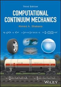
An updated and expanded edition of the popular guide to basic continuum mechanics and computational techniques This updated third edition of the popular reference covers state-of-the-art computational techniques for basic continuum mechanics modeling of both small and large deformations. Approaches to developing complex models are described in detail, and numerous examples are presented demonstrating how computational algorithms can be developed using basic continuum mechanics approaches. The integration of geometry and analysis for the study of the motion and behaviors of materials under varying conditions is an increasingly popular approach in continuum mechanics, and absolute nodal coordinate formulation (ANCF) is rapidly emerging as the best way to achieve that integration. At the same time, simulation software is undergoing significant changes which will lead to the seamless fusion of CAD, finite element, and multibody system computer codes in one computational environment. Computational Continuum Mechanics, Third Edition is the only book to provide in-depth coverage of the formulations required to achieve this integration. * Provides detailed coverage of the absolute nodal coordinate formulation (ANCF), a popular new approach to the integration of geometry and analysis * Provides detailed coverage of the floating frame of reference (FFR) formulation, a popular well-established approach for solving small deformation problems * Supplies numerous examples of how complex models have been developed to solve an array of real-world problems * Covers modeling of both small and large deformations in detail * Demonstrates how to develop computational algorithms using basic continuum mechanics approaches Computational Continuum Mechanics, Third Edition is designed to function equally well as a text for advanced undergraduates and first-year graduate students and as a working reference for researchers, practicing engineers, and scientists working in computational mechanics, bio-mechanics, computational biology, multibody system dynamics, and other fields of science and engineering using the general continuum mechanics theory.
Sie lesen das E-Book in den Legimi-Apps auf:
Seitenzahl: 581
Veröffentlichungsjahr: 2018
Ähnliche


TABLE OF CONTENTS
COVER
TITLE PAGE
COPYRIGHT
PREFACE
CHAPTER 1: INTRODUCTION
1.1 MATRICES
1.2 VECTORS
1.3 SUMMATION CONVENTION
1.4 CARTESIAN TENSORS
1.5 POLAR DECOMPOSITION THEOREM
1.6 D'ALEMBERT'S PRINCIPLE
1.7 VIRTUAL WORK PRINCIPLE
1.8 APPROXIMATION METHODS
1.9 DISCRETE EQUATIONS
1.10 MOMENTUM, WORK, AND ENERGY
1.11 PARAMETER CHANGE AND COORDINATE TRANSFORMATION
PROBLEMS
CHAPTER 2: KINEMATICS
2.1 MOTION DESCRIPTION
2.2 STRAIN COMPONENTS
2.3 OTHER DEFORMATION MEASURES
2.4 DECOMPOSITION OF DISPLACEMENT
2.5 VELOCITY AND ACCELERATION
2.6 COORDINATE TRANSFORMATION
2.7 OBJECTIVITY
2.8 CHANGE OF VOLUME AND AREA
2.9 CONTINUITY EQUATION
2.10 REYNOLDS' TRANSPORT THEOREM
2.11 EXAMPLES OF DEFORMATION
2.12 GEOMETRY CONCEPTS
PROBLEMS
CHAPTER 3: FORCES AND STRESSES
3.1 EQUILIBRIUM OF FORCES
3.2 TRANSFORMATION OF STRESSES
3.3 EQUATIONS OF EQUILIBRIUM
3.4 SYMMETRY OF THE CAUCHY STRESS TENSOR
3.5 VIRTUAL WORK OF THE FORCES
3.6 DEVIATORIC STRESSES
3.7 STRESS OBJECTIVITY
3.8 ENERGY BALANCE
PROBLEMS
CHAPTER 4: CONSTITUTIVE EQUATIONS
4.1 GENERALIZED HOOKE'S LAW
4.2 ANISOTROPIC LINEARLY ELASTIC MATERIALS
4.3 MATERIAL SYMMETRY
4.4 HOMOGENEOUS ISOTROPIC MATERIAL
4.5 PRINCIPAL STRAIN INVARIANTS
4.6 SPECIAL MATERIAL MODELS FOR LARGE DEFORMATIONS
4.7 LINEAR VISCOELASTICITY
4.8 NONLINEAR VISCOELASTICITY
4.9 A SIMPLE VISCOELASTIC MODEL FOR ISOTROPIC MATERIALS
4.10 FLUID CONSTITUTIVE EQUATIONS
4.11 NAVIER–STOKES EQUATIONS
PROBLEMS
CHAPTER 5: FINITE ELEMENT FORMULATION: LARGE-DEFORMATION, LARGE-ROTATION PROBLEM
5.1 DISPLACEMENT FIELD
5.2 ELEMENT CONNECTIVITY
5.3 INERTIA AND ELASTIC FORCES
5.4 EQUATIONS OF MOTION
5.5 NUMERICAL EVALUATION OF THE ELASTIC FORCES
5.6 FINITE ELEMENTS AND GEOMETRY
5.7 TWO-DIMENSIONAL EULER–BERNOULLI BEAM ELEMENT
5.8 TWO-DIMENSIONAL SHEAR DEFORMABLE BEAM ELEMENT
5.9 THREE-DIMENSIONAL CABLE ELEMENT
5.10 THREE-DIMENSIONAL BEAM ELEMENT
5.11 THIN-PLATE ELEMENT
5.12 HIGHER-ORDER PLATE ELEMENT
5.13 BRICK ELEMENT
5.14 ELEMENT PERFORMANCE
5.15 OTHER FINITE ELEMENT FORMULATIONS
5.16 UPDATED LAGRANGIAN AND EULERIAN FORMULATIONS
5.17 CONCLUDING REMARKS
PROBLEMS
CHAPTER 6: FINITE ELEMENT FORMULATION: SMALL-DEFORMATION, LARGE-ROTATION PROBLEM
6.1 BACKGROUND
6.2 ROTATION AND ANGULAR VELOCITY
6.3 FLOATING FRAME OF REFERENCE (FFR)
6.4 INTERMEDIATE ELEMENT COORDINATE SYSTEM
6.5 CONNECTIVITY AND REFERENCE CONDITIONS
6.6 KINEMATIC EQUATIONS
6.7 FORMULATION OF THE INERTIA FORCES
6.8 ELASTIC FORCES
6.9 EQUATIONS OF MOTION
6.10 COORDINATE REDUCTION
6.11 INTEGRATION OF FINITE ELEMENT AND MULTIBODY SYSTEM ALGORITHMS
PROBLEMS
CHAPTER 7: COMPUTATIONAL GEOMETRY AND FINITE ELEMENT ANALYSIS
7.1 GEOMETRY AND FINITE ELEMENT METHOD
7.2 ANCF GEOMETRY
7.3 BEZIER GEOMETRY
7.4 B-SPLINE CURVE REPRESENTATION
7.5 CONVERSION OF B-SPLINE GEOMETRY TO ANCF GEOMETRY
7.6 ANCF AND B-SPLINE SURFACES
7.7 STRUCTURAL AND NONSTRUCTURAL DISCONTINUITIES
PROBLEMS
CHAPTER 8: PLASTICITY FORMULATIONS
8.1 ONE-DIMENSIONAL PROBLEM
8.2 LOADING AND UNLOADING CONDITIONS
8.3 SOLUTION OF THE PLASTICITY EQUATIONS
8.4 GENERALIZATION OF THE PLASTICITY THEORY: SMALL STRAINS
8.5
J
2
FLOW THEORY WITH ISOTROPIC/KINEMATIC HARDENING
8.6 NONLINEAR FORMULATION FOR HYPERELASTIC–PLASTIC MATERIALS
8.7
HYPERELASTIC–PLASTIC
J
2
FLOW THEORY
PROBLEMS
REFERENCES
INDEX
End User License Agreement
Pages
ix
x
xi
xii
`
`
`
`
`
`
`
`
`
`
`
`
`
`
`
`
`
`
`
`
`
`
`
`
`
`
`
`
`
`
`
`
`
`
`
`
`
`
`
`
`
`
`
`
`
`
`
`
`
`
`
`
`
`
`
`
`
`
`
`
`
`
`
`
`
`
`
`
`
`
`
`
`
`
`
`
`
`
`
`
`
`
`
`
`
`
`
`
`
`
`
`
`
`
`
`
`
`
`
`
`
`
`
`
`
`
`
`
`
`
`
`
`
`
`
`
`
`
`
`
`
`
`
`
`
`
`
`
`
`
`
`
`
`
`
`
`
`
`
`
`
`
`
`
`
`
`
`
`
`
`
`
`
`
`
`
`
`
`
`
`
`
`
`
`
`
`
`
`
`
`
`
`
`
`
`
`
`
`
`
`
`
`
`
`
`
`
`
`
`
`
`
`
`
`
`
`
`
`
`
`
`
`
`
`
`
`
`
`
`
`
`
`
`
`
`
`
`
`
`
`
`
`
`
`
`
`
`
`
`
`
`
`
`
`
`
`
`
`
`
`
`
`
`
`
`
`
`
`
`
`
`
`
`
`
`
`
`
`
`
`
`
`
`
`
`
`
`
`
`
`
`
`
`
`
`
`
`
`
`
`
`
`
`
`
`
`
`
`
`
`
`
`
`
`
`
`
`
`
`
`
`
`
`
`
`
`
`
`
`
`
`
`
`
`
`
`
`
`
`
`
`
`
`
`
`
`
`
`
`
`
339
340
341
342
343
344
345
346
347
348
349
350
Guide
Cover
Table of Contents
Preface
Begin Reading
List of Illustrations
CHAPTER 1: INTRODUCTION
Figure 1 Rigid-body coordinates
Figure 2 Two-dimensional beam
Figure 3 Space curve
Figure 4 Slider crank mechanism
Figure 5 Deformation measurement.
CHAPTER 2: KINEMATICS
Figure 1 Reference and current configurations
Figure 2 Planar beam
Figure 3 Rigid-body motion
Figure 4 Floating frame of reference
Figure 5 One current configuration and two reference coordinate systems (strain transformation)
Figure 6 Two current configurations and one reference coordinate system (objectivity)
Figure 7 Nanson's formula
Figure 8 Initial geometry
Figure 9 Geometry description
CHAPTER 3: FORCES AND STRESSES
Figure 1 Surface traction
Figure 2 Tetrahedral surface forces
Figure 3 Surface forces
CHAPTER 4: CONSTITUTIVE EQUATIONS
Figure 1 Standard model
Figure 2 Generalization
CHAPTER 5: FINITE ELEMENT FORMULATION: LARGE-DEFORMATION, LARGE-ROTATION PROBLEM
Figure 1 Finite element discretization
Figure 2 Three-dimensional beam element
Figure 3 Element connectivity
Figure 4 Initial geometry
Figure 5 ANCF description of curved geometry
Figure 6 Surface geometry. (a) Elliptic surface, (b) hyperbolic surface, (c) parabolic surface, and (d) planar surface
Figure 7 Plate element
Figure 8 ANCF brick element
Figure 9 ANCF total Lagrangian fluid simulation (Wei et al., 2015)
Figure 10 Tracked vehicles
Figure 11 Tire assembly
CHAPTER 6: FINITE ELEMENT FORMULATION: SMALL-DEFORMATION, LARGE-ROTATION PROBLEM
Figure 1 Two-dimensional beam element
Figure 2 Floating frame of reference
Figure 3 Body kinematics
Figure 4 Intermediate element coordinate system
Figure 5 Slider crank mechanism
Figure 6 Scaling of the elastic coordinates
Figure 7 Liquid sloshing results using ANCF finite elements (Wei et al., 2015)
Figure 8 Liquid sloshing results using the FFR formulation (Wei et al., 2015)
CHAPTER 7: COMPUTATIONAL GEOMETRY AND FINITE ELEMENT ANALYSIS
Figure 1 Gradients and control points
Figure 2 B-spline curve
Figure 3 Knot insertion
Figure 4 Structural and nonstructural discontinuities
CHAPTER 8: PLASTICITY FORMULATIONS
Figure 1 Intermediate plastic configuration
List of Tables
CHAPTER 5: FINITE ELEMENT FORMULATION: LARGE-DEFORMATION, LARGE-ROTATION PROBLEM
Table 1 ANCF Description of Curved Geometry
COMPUTATIONAL CONTINUUM MECHANICS THIRD EDITION
THIRD EDITION
AHMED A. SHABANA
Richard and Loan Hill Professor of Engineering University of Illinois at Chicago Chicago, Illinois, USA
This edition first published 2018
© 2018 John Wiley & Sons Ltd
First edition published 2008 by Cambridge University Press
Second edition published 2012 by Cambridge University Press
All rights reserved. No part of this publication may be reproduced, stored in a retrieval system, or transmitted, in any form or by any means, electronic, mechanical, photocopying, recording or otherwise, except as permitted by law. Advice on how to obtain permission to reuse material from this title is available at http://www.wiley.com/go/permissions.
The right of Ahmed A. Shabana to be identified as the author of this work has been asserted in accordance with law.
Registered Office(s)
John Wiley & Sons, Inc., 111 River Street, Hoboken, NJ 07030, USA
John Wiley & Sons Ltd, The Atrium, Southern Gate, Chichester, West Sussex, PO19 8SQ, UK
Editorial Office
The Atrium, Southern Gate, Chichester, West Sussex, PO19 8SQ, UK
For details of our global editorial offices, customer services, and more information about Wiley products visit us at www.wiley.com.
Wiley also publishes its books in a variety of electronic formats and by print-on-demand. Some content that appears in standard print versions of this book may not be available in other formats.
Limit of Liability/Disclaimer of Warranty
While the publisher and authors have used their best efforts in preparing this work, they make no representations or warranties with respect to the accuracy or completeness of the contents of this work and specifically disclaim all warranties, including without limitation any implied warranties of merchantability or fitness for a particular purpose. No warranty may be created or extended by sales representatives, written sales materials or promotional statements for this work. The fact that an organization, website, or product is referred to in this work as a citation and/or potential source of further information does not mean that the publisher and authors endorse the information or services the organization, website, or product may provide or recommendations it may make. This work is sold with the understanding that the publisher is not engaged in rendering professional services. The advice and strategies contained herein may not be suitable for your situation. You should consult with a specialist where appropriate. Further, readers should be aware that websites listed in this work may have changed or disappeared between when this work was written and when it is read. Neither the publisher nor authors shall be liable for any loss of profit or any other commercial damages, including but not limited to special, incidental, consequential, or other damages.
Library of Congress Cataloging-in-Publication Data:
Names: Shabana, Ahmed A., 1951- author.
Title: Computational continuum mechanics / by Ahmed A. Shabana.
Description: Third edition. | Hoboken, NJ, USA : Wiley, [2018] | Includes bibliographical references and index. |
Identifiers: LCCN 2017032713 (print) | LCCN 2017035575 (ebook) | ISBN 9781119293231 (ePDF) | ISBN 9781119293200 (ePUB) | ISBN 9781119293217 (cloth)
Subjects: LCSH: Continuum mechanics. | Engineering mathematics.
Classification: LCC QA808.2 (ebook) | LCC QA808.2 .S46 2018 (print) | DDC 531-dc23
LC record available at https://lccn.loc.gov/2017032713
Cover design by Wiley
Cover Images: (Gas Tank) © scanrail/Gettyimages; (Tire) © Rellas/Gettyimages; (Water) © molotovcoketail/Gettyimages; (Wave) © Shannon Stent/iStockphoto; (Leaf Springs) © ABBPhoto/Gettyimages
Preface
Nonlinear continuum mechanics is one of the fundamental subjects that form the foundation of modern computational mechanics. The study of the motion and behavior of materials under different loading conditions requires understanding of basic, general, and nonlinear kinematic and dynamic relationships that are covered in continuum mechanics courses. The finite element method, on the other hand, has emerged as a powerful tool for solving many problems in engineering and physics. The finite element method became a popular and widely used computational approach because of its versatility and generality in solving large-scale and complex physics and engineering problems. Nonetheless, the success of using the continuum-mechanics-based finite element method in the analysis of the motion of bodies that experience general displacements, including arbitrary large rotations, has been limited. The solution to this problem requires resorting to some of the basic concepts in continuum mechanics and putting the emphasis on developing sound formulations that satisfy the principles of mechanics. Some researchers, however, have tried to solve fundamental formulation problems using numerical techniques that lead to approximations. Although numerical methods are an integral part of modern computational algorithms and can be effectively used in some applications to obtain efficient and accurate solutions, it is the opinion of many researchers that numerical methods should only be used as a last resort to fix formulation problems. Sound formulations must be first developed and tested to make sure that these formulations satisfy the basic principles of mechanics. The equations that result from the use of the analytically correct formulations can then be solved using numerical methods.
This book is focused on presenting the nonlinear theory of continuum mechanics and demonstrating its use in developing nonlinear computer formulations that can be used in the large displacement dynamic analysis. To this end, the basic concepts used in continuum mechanics are first presented and then used to develop nonlinear general finite element formulations for the large displacement analysis. Two nonlinear finite element dynamic formulations will be considered in this book. The first is a general large-deformation finite element formulation, whereas the second is a formulation that can be used efficiently to solve small-deformation problems that characterize very and moderately stiff structures. In this latter case, an elaborate method for eliminating the unnecessary degrees of freedom must be used in order to be able to efficiently obtain a numerical solution. An attempt has been made to present the materials in a clear and systematic manner with the assumption that the reader has only basic knowledge in matrix and vector algebra as well as basic knowledge of dynamics. The book is designed for a course at the senior undergraduate and first-year graduate level. It can also be used as a reference for researchers and practicing engineers and scientists who are working in the areas of computational mechanics, biomechanics, computational biology, multibody system dynamics, and other fields of science and engineering that are based on the general continuum mechanics theory.
In Chapter 1, matrix, vector, and tensor notations are introduced. These notations will be repeatedly used in all chapters of the book, and therefore, it is necessary that the reader reviews this chapter in order to be able to follow the presentation in subsequent chapters. The polar decomposition theorem, which is fundamental in continuum and computational mechanics, is also presented in this chapter. D'Alembert's principle and the principle of virtual work can be used to systematically derive the equations of motion of physical systems. These two important principles are discussed and the relationship between them is explained. The use of a finite dimensional model to describe the continuum motion is also discussed and the procedure for developing the discrete equations of motion is outlined. The principles of momentum and principle of work and energy are presented, and the problems associated with some of the finite element formulations that violate these analytical mechanics principles are discussed. Chapter 1 also provides a discussion on the definitions of the gradient vectors that are used in continuum mechanics to define the strain components.
In Chapter 2, the general kinematic displacement equations of a continuum are developed and used to define the strain components. The Green–Lagrange strains and the Almansi or Eulerian strains are introduced. The Green–Lagrange strains are defined in the reference configuration, whereas the Almansi or Eulerian strains are defined in the current deformed configuration. The relationships between these strain components are established and used to shed light on the physical meaning of the strain components. Other deformation measures as well as the velocity and acceleration equations are also defined in this chapter. The important issue of objectivity that must be considered when large deformations and inelastic formulations are used is discussed. The equations that govern the change of volume and area, the conservation of mass, and examples of deformation modes are also presented in this chapter.
Forces and stresses are discussed in Chapter 3. Equilibrium of forces acting on an infinitesimal material element is used to define the Cauchy stresses, which are used to develop the partial differential equations of equilibrium. The transformation of the stress components and the symmetry of the Cauchy stress tensor are among the topics discussed in this chapter. The virtual work of the forces due to the change of the shape of the continuum is defined. The deviatoric stresses, stress objectivity, and energy balance equations are also discussed in Chapter 3.
The definition of the strain and stress components is not sufficient to describe the motion of a continuum. One must define the relationship between the stresses and strains using the constitutive equations that are discussed in Chapter 4. In Chapter 4, the generalized Hooke's law is introduced and the assumptions used in the definition of homogeneous isotropic materials are outlined. The principal strain invariants and special large-deformation material models are discussed. The linear and nonlinear viscoelastic material behavior is also discussed in Chapter 4.
Nonlinear finite element formulations are discussed in Chapters 5 and 6. Two formulations are discussed in these two chapters. The first is a large-deformation finite element formulation, which is discussed in Chapter 5. This formulation, called the absolute nodal coordinate formulation (ANCF), is based on a continuum mechanics theory and employs position gradients as coordinates. It leads to a unique displacement and rotation fields and imposes no restrictions on the amount of rotation or deformation within the finite element. The absolute nodal coordinate formulation has some unique features that distinguish it from other existing large-deformation finite element formulations: it leads to a constant mass matrix; it leads to zero centrifugal and Coriolis forces; it automatically satisfies the principles of mechanics; it correctly describes an arbitrary rigid-body motion including finite rotations; and it can be used to develop several beam, plate, and shell elements that relax many of the assumptions used in classical theorems. When using ANCF finite elements, no distinction is made between plate and shell elements since shell geometry can be systematically obtained using the nodal coordinates in the reference configuration.
Clearly, large-deformation finite element formulations can also be used to solve small-deformation problems. However, it is not recommended to use a large-deformation finite element formulation to solve a small-deformation problem. Large-deformation formulations do not exploit some particular features of small-deformation problems, and therefore, such formulations can be very inefficient in the solution of stiff and moderately stiff systems. The development of an efficient small-deformation finite element formulation that correctly describes an arbitrary rigid-body motion requires the use of more elaborate techniques in order to define a local linear problem without compromising the ability of the method to describe large-displacement, small-deformation behavior. The finite element floating frame of reference (FFR) formulation, widely used in the analysis of small deformations, is discussed in Chapter 6. This formulation allows eliminating high-frequency modes that do not have a significant effect on the solution, thereby leading to a lower-dimension dynamic model that can be efficiently solved using numerical and computer methods.
Although finite element (FE) formulations are based on polynomial representations, the polynomial-based geometric representation used in computer-aided design (CAD) methods cannot be converted exactly to the kinematic description used in many existing FE formulations. For this reason, converting a CAD model to an FE mesh can be costly and time-consuming. CAD software systems use computational geometry methods such as B-spline and Non-Uniform Rational B-Splines (NURBS). These methods can describe accurately complex geometry. The relationship between these CAD geometry methods and the FE formulations presented in this book are discussed in Chapter 7. As explained in Chapter 7, modeling modern engineering and physics systems requires the successful integration of computer-aided design and analysis (I-CAD-A) by developing an efficient interface between CAD systems and analysis tools or by developing a new mechanics based CAD/analysis system.
In many engineering applications, plastic deformations occur due to excessive forces and impact as well as thermal loads. Several plasticity formulations are presented in Chapter 8. First, a one-dimensional theory is used in order to discuss the main concepts and solution procedures used in the plasticity analysis. The theory is then generalized to the three-dimensional analysis for the case of small strains. Large strain nonlinear plasticity formulations as well as the J2 flow theory are among the topics discussed in Chapter 8.
I would like to thank many students and colleagues with whom I worked for several years on the subject of flexible body dynamics. I was fortunate to collaborate with excellent students and colleagues who educated me in this important field of computational mechanics. In particular, I would like to thank my doctorate students, Bassam Hussein, Luis Maqueda, Mohil Patel, Brian Tinsley, and Liang Wang, who provided solutions for several of examples and figures presented in several chapters of the book. I would also like to thank my family for their help, patience, and understanding during the time of preparing this book.
Ahmed A. Shabana Chicago, IL 2016
CHAPTER 1INTRODUCTION
Matrix, vector, and tensor algebras are often used in the theory of continuum mechanics in order to have a simpler and more tractable presentation of the subject. In this chapter, the mathematical preliminaries required to understand the matrix, vector, and tensor operations used repeatedly in this book are presented. Principles of mechanics and approximation methods that represent the basis for the formulation of the kinematic and dynamic equations developed in this book are also reviewed in this chapter. In the first two sections of this chapter, matrix and vector notations are introduced and some of their important identities are presented. Some of the vector and matrix results are presented without proofs with the assumption that the reader has some familiarity with matrix and vector notations. In Section 3, the summation convention, which is widely used in continuum mechanics texts, is introduced. This introduction is made despite the fact that the summation convention is rarely used in this book. Tensor notations, on the other hand, are frequently used in this book and, for this reason, tensors are discussed in Section 4. In Section 5, the polar decomposition theorem, which is fundamental in continuum mechanics, is presented. This theorem states that any nonsingular square matrix can be decomposed as the product of an orthogonal matrix and a symmetric matrix. Other matrix decompositions that are used in computational mechanics are also discussed. In Section 6, D'Alembert's principle is introduced, while Section 7 discusses the virtual work principle. The finite element method is often used to obtain finite dimensional models of continuous systems that in reality have infinite number of degrees of freedom. To introduce the reader to some of the basic concepts used to obtain finite dimensional models, discussions of approximation methods are included in Section 8. The procedure for developing the discrete equations of motion is outlined in Section 9, while the principle of conservation of momentum and the principle of work and energy are discussed in Section 10. In continuum mechanics, the gradients of the position vectors can be determined by differentiation with respect to different parameters. The change of parameters can lead to the definitions of strain components in different directions. This change of parameters, however, does not change the coordinate system in which the gradient vectors are defined. The effect of the change of parameters on the definitions of the gradients is discussed in Section 11.
1.1 MATRICES
In this section, some identities, results, and properties from matrix algebra that are used repeatedly in this book are presented. Some proofs are omitted, with the assumption that the reader is familiar with the subject of linear algebra.
Definitions
An m × n matrix A is an ordered rectangular array, which can be written in the following form:
where aij is the ijth element that lies in the ith row and jth column of the matrix. Therefore, the first subscript i refers to the row number and the second subscript j refers to the column number. The arrangement of Equation 1 shows that the matrix A has m rows and n columns. If m = n, the matrix is said to be square; otherwise, the matrix is said to be rectangular. The transpose of an m × n matrix A is an n × m matrix, denoted as AT, which is obtained from A by exchanging the rows and columns, that is, AT = .
A diagonal matrix is a square matrix whose only nonzero elements are the diagonal elements, that is, aij = 0 if i ≠ j. An identity or unit matrix, denoted as I, is a diagonal matrix that has all its diagonal elements equal to one. The null or zero matrix is a matrix that has all its elements equal to zero. The trace of a square matrix A is the sum of all its diagonal elements, that is,
This equation shows that tr(I) = n, where I is the identity matrix and n is the dimension of the matrix.
A square matrix A is said to be symmetric if
A square matrix is said to be skew symmetric if
This equation shows that all the diagonal elements of a skew-symmetric matrix must be equal to zero. That is, if A is a skew-symmetric matrix with dimension n, then aii = 0 for i = 1, 2,…, n. Any square matrix can be written as the sum of a symmetric matrix and a skew-symmetric matrix. For example, if B is a square matrix, B can be written as
where and are, respectively, symmetric and skew-symmetric matrices defined as
Skew-symmetric matrices are used in continuum mechanics to characterize the rotations of the material elements.
Determinant
The determinant of an n × n square matrix A, denoted as |A| or det(A), is a scalar quantity. In order to be able to define the unique value of the determinant, some basic definitions have to be introduced. The minor Mij corresponding to the element aij is the determinant of a matrix obtained by deleting the ith row and jth column from the original matrix A. The cofactor Cij of the element aij is defined as
Using this definition, the determinant of the matrix A can be obtained in terms of the cofactors of the elements of an arbitrary row j as follows:
One can show that the determinant of a diagonal matrix is equal to the product of the diagonal elements, and the determinant of a matrix is equal to the determinant of its transpose; that is, if A is a square matrix, then |A| = |AT|. Furthermore, the interchange of any two columns or rows only changes the sign of the determinant. It can also be shown that if the matrix has linearly dependent rows or linearly dependent columns, the determinant is equal to zero. A matrix whose determinant is equal to zero is called a singular matrix. For an arbitrary square matrix, singular or nonsingular, it can be shown that the value of the determinant does not change if any row or column is added or subtracted from another. It can be also shown that the determinant of the product of two matrices is equal to the product of their determinants. That is, if A and B are two square matrices, then |AB| = |A||B|.
As will be shown in this book, the determinants of some of the deformation measures used in continuum mechanics are used in the formulation of the energy expressions. Furthermore, the relationship between the volumes of a continuum in the undeformed state and the deformed state is expressed in terms of the determinant of the matrix of position vector gradients. Therefore, if the elements of a square matrix depend on a parameter, it is important to be able to determine the derivatives of the determinant with respect to this parameter. Using Equation 8, one can show that if the elements of the matrix A depend on a parameter t, then
where . The use of this equation is demonstrated by the following example.
EXAMPLE 1.1
Consider the matrix J defined as
where Jij = ∂ri/∂xj, and r and x are the vectors
That is, the elements of the vector r are functions of the coordinates x1, x2, and x3 and the parameter t. If J = |J| is the determinant of J, prove that
where , i, j = 1, 2, 3.
Solution: Using Equation 9, one can write
where Cij is the cofactor associated with element Jij. Note that the preceding equation can be written as
In this equation,
Using this expansion, one can show that
Similarly, one can show that
Using the preceding equations, it is clear that
This matrix identity is important and is used in this book to evaluate the rate of change of the determinant of the matrix of position vector gradients in terms of important deformation measures.
Inverse and Orthogonality
A square matrix A−1 that satisfies the relationship
where I is the identity matrix, is called the inverse of the matrix A. The inverse of the matrix A is defined as
where Ct is the adjoint of the matrix A. The adjoint matrix Ct is the transpose of the matrix of the cofactors (Cij) of the matrix A. One can show that the determinant of the inverse |A−1| is equal to 1/|A|.
A square matrix is said to be orthogonal if
Note that in the case of an orthogonal matrix A, one has
That is, the inverse of an orthogonal matrix is equal to its transpose. One can also show that if A is an orthogonal matrix, then |A| = ±1; and if A1 and A2 are two orthogonal matrices that have the same dimensions, then their product A1A2 is also an orthogonal matrix.
Examples of orthogonal matrices are the 3 × 3 transformation matrices that define the orientation of coordinate systems. In the case of a right-handed coordinate system, one can show that the determinant of the transformation matrix is +1; this is a proper orthogonal transformation. If the right-hand rule is not followed, the determinant of the resulting orthogonal transformation is equal to −1, which is animproper orthogonal transformation, such as in the case of a reflection.
Matrix Operations
The sum of two matrices A = (aij) and B = (bij) is defined as
In order to add two matrices, they must have the same dimensions. That is, the two matrices A and B must have the same number of rows and same number of columns in order to apply Equation 14.
The product of two matrices A and B is another matrix C defined as
The element cij of the matrix C is defined by multiplying the elements of the ith row in A by the elements of the jth column in B according to the rule
Therefore, the number of columns in A must be equal to the number of rows in B. If A is an m × n matrix and B is an n × p matrix, then C is an m × p matrix. In general, AB ≠ BA. That is, matrix multiplication is not commutative. The associative law for matrix multiplication, however, is valid; that is, (AB)C = A(BC) = ABC, provided consistent dimensions of the matrices A, B, and C are used.
1.2 VECTORS
Vectors can be considered special cases of matrices. An n-dimensional vector a can be written as
Therefore, it is assumed that the vector is a column, unless it is transposed to make it a row.
Because vectors can be treated as columns of matrices, the addition of vectors is the same as the addition of column matrices. That is, if a = (ai) and b = (bi) are two n-dimensional vectors, then a + b = (ai + bi). Three different types of products, however, can be used with vectors. These are the dot product, the cross product, and the outer or dyadic product. The result of the dot product of two vectors is a scalar, the result of the cross product is a vector, and the result of the dyadic product is a matrix. These three different types of products are discussed in the following sections.
Dot Product
The dot, inner, or scalar product of two vectors a and b is defined as
Note that the two vectors a and b must have the same dimension. The two vectors a and b are said to be orthogonal if a · b = aTb = 0. The norm, magnitude, or length of an n-dimensional vector is defined as
It is clear from this definition that the norm is always a positive number, and it is equal to zero only when a is the zero vector, that is, all the components of a are equal to zero.
In the special case of three-dimensional vectors, the dot product of two arbitrary three-dimensional vectors a and b can be written in terms of their norms as a · b = |a| |b| cos α, where α is the angle between the two vectors. A vector is said to be a unit vector if its norm is equal to one. It is clear from the definition of the norm given by Equation 19 that the absolute value of any element of a unit vector must not exceed one. A unit vector along the vector a can be simply obtained by dividing the vector by its norm. That is, = a/|a|. The dot product b · = |b| cos α defines the component of the vector b along the unit vector , where α is the angle between the two vectors. The projection of the vector b on a plane perpendicular to the unit vector is defined by the equation b − (b · ) , or equivalently by b − (|b| cos α) .
Cross Product
The vector cross product is defined for three-dimensional vectors only. Let a and b be two three-dimensional vectors defined in the same coordinate system. Unit vectors along the axes of the coordinate system are denoted by the vectors i1, i2, and i3. These base vectors are orthonormal, that is,
where δij is the Kronecker delta defined as
The cross product of the two vectors a and b is defined as
which can be written as
This equation can be written as
where ã is the skew-symmetric matrix associated with the vector a and is defined as
One can show that the determinant of the skew-symmetric matrix ã is equal to zero. That is, |ã| = 0. One can also show that
In this equation, is the skew-symmetric matrix associated with the vector b. If a and b are two parallel vectors, it can be shown that a × b = 0. That is, the cross product of two parallel vectors is equal to zero.
Dyadic Product
Another form of vector product used in this book is the dyadic or outer product. Whereas the dot product leads to a scalar and the cross product leads to a vector, the dyadic product leads to a matrix. The dyadic product of two vectors a and b is written as ab and is defined as
Note that, in general, . One can show that the dyadic product of two vectors satisfies the following identities:
In Equation 28, it is assumed that the vectors have the appropriate dimensions. The dyadic product satisfies the following additional properties for any arbitrary vectors u, v, v1, and v2 and a square matrix A:
The second and third identities of Equation 29 show that . This result is important in understanding the rule of transformation of the second-order tensors that will be used repeatedly in this book. It is left to the reader as an exercise to verify the identities of Equation 29.
EXAMPLE 1.2
Consider the two vectors a = [a1a2]T and b = [b1b2b3]T. The dyadic product of these two vectors is given by
For a given vector c = [c1c2c3]T, one has
Also note that the dyadic product can be written as
It follows that if R is a 2 × 2 matrix, one has
Several important identities can be written in terms of the dyadic product. Some of these identities are valuable in the computer implementation of the dynamic formulations presented in this book because the use of these identities can lead to significant simplification of the computational algorithms. By using these identities, one can avoid rewriting codes that perform the same mathematical operations, thereby saving effort and time by producing a manageable computer code. One of these identities that can be written in terms of the dyadic product is obtained in the following example.
EXAMPLE 1.3
In the computer implementation of the formulations presented in this book, one may require differentiating a unit vector along the vector r with respect to the components of the vector r. Such a differentiation can be written in terms of the dyadic product. To demonstrate this, we write
where |r| = . It follows that
This equation can be written in terms of the dyadic product as
Projection
If is a unit vector, the component of a vector b along the unit vector is defined by the dot product b · . The projection of b along is then defined as (b · ), which can be written using Equation 28 as (b · ) = ()b. The matrix P = defines a projection matrix. For an arbitrary integer n, one can show that the projection matrix P satisfies the identity Pn = P. This is an expected result because the vector ()b = Pb is defined along and has no components in other directions. Other projections should not change this result.
The projection of the vector b on a plane perpendicular to the unit vector is defined as b − (b · ), which can be written using the dyadic product as (I − )b. This equation defines another projection matrix Pp = I − , or simply Pp = I − P. For an arbitrary integer n, one can show that the projection matrix Pp satisfies the identity = Pp. Furthermore, PPp = 0 and P + Pp = I.
EXAMPLE 1.4
Consider the vector a = [1 2 0]T. A unit vector along a is defined as
The projection matrix P associated with this unit vector can be written as
It follows that
The projection matrix Pp is defined in this example as
Note that . Successive application of this equation shows that = Pp. The reader can verify this fact by the data given in this example.
1.3 SUMMATION CONVENTION
In this section, another convenient notational method, the summation convention, is discussed. The summation convention is used in most books on the subject of continuum mechanics. According to this convention, summation over the values of the indices is automatically assumed if an index is repeated in an expression. For example, if an index j takes the values from 1 to n, then in the summation convention, one has
and
The repeated index used in the summation is called the dummy index, an example of which is the index j used in the preceding equation. If the index is not a dummy index, it is called a free index, an example of which is the index i used in Equation 31. It follows that the trace of a matrix A can be written using the summation convention as tr(A) = aii. The dot product between two n-dimensional vectors a and b can be written using the summation convention as a · b = aTb = aibi. The product of a matrix A and a vector b is another vector c = Ab whose components can be written using the summation convention as ci = aijbj. Here, i is the free index and j is the dummy index.
Unit Dyads
The dyadic product between two vectors can also be written using the summation convention. For example, in the case of three-dimensional vectors, one can define the base vectors ik, k = 1, 2, 3. Any three-dimensional vector can be written in terms of these base vectors using the summation convention as a = aiii = a1i1 + a2i2 + a3i3. The dyadic product of two vectors a and b can then be written as
For example, if ii = i1 = [1 0 0]T, ij = i2 = [0 1 0]T, and a and b are arbitrary three-dimensional vectors, one can show that the dyadic product of the preceding equation can be written in the following matrix form:
The dyadic products of the base vectors are called the unit dyads. Using this notation, the dyadic product can be generalized to the products of three or more vectors. For example, the triadic product of the vectors a, b, and c can be written as abc = (aiii) (bjij) (ckik) = aibjck(iiijik). In this book, the familiar summation sign ∑ will be used for the most part, instead of the summation convention.
1.4 CARTESIAN TENSORS
It is clear from the preceding section that a dyadic product is a linear combination of unit dyads. The second-order Cartesian tensor is defined as a linear combination of dyadic products. A second-order Cartesian tensor A takes the following form:
where aij are called the components of A. Using the analysis presented in the preceding section, one can show that the second-order tensor can be written in the matrix form of Equation 33. Nonetheless, for a given second-order tensor A, one cannot in general find two vectors a and b such that A = ab.
The unit or identity tensor can be written in terms of the base vectors as
Using the definition of the second-order tensor as a linear combination of dyadic products, one can show, as previously mentioned, that the components of any second-order tensor can be arranged in the form of a 3 × 3 matrix. In continuum mechanics, the elements of tensors represent physical quantities such as moments of inertia, strains, and stresses. These elements can be defined in any coordinate system. The coordinate systems used depend on the formulation used to obtain the equilibrium equations. It is, therefore, important that the reader understands the rule of the coordinate transformation of tensors and recognizes that such a transformation leads to the definition of the same physical quantities in different frames of reference or different directions. One must also distinguish between the transformation of vectors and the change of parameters. The latter does not change the coordinate system in which the vectors are defined. This important difference will be discussed in more detail before concluding this chapter.
A tensor that has the same components in any coordinate system is called an isotropic tensor. An example of isotropic tensors is the unit tensor. It can be shown that second-order isotropic tensors take only one form and can be written as αI, where α is a scalar and I is the unit or the identity tensor. Second-order isotropic tensors are sometimes called spherical tensors.
Double Product or Double Contraction
If A is a second-order tensor, the contraction of this tensor to a scalar is defined as , where tr denotes the trace of the matrix (sum of the diagonal elements) (Aris 1962). It can be shown that the trace of a second-order tensor is invariant under orthogonal coordinate transformations. In addition to the trace, the determinant of A is invariant under orthogonal coordinate transformation. This important result can also be obtained in the case of second-order tensors using the facts that the determinant of an orthogonal matrix is equal to ±1 and the determinant of the product of matrices is equal to the product of the determinants of these matrices.
If A and B are second-order tensors, the double product or double contraction is defined as
Using the properties of the trace, one can show that
where aij and bij are, respectively, the elements of the tensors A and B. If a, b, u, and v are arbitrary vectors and A is a second-order tensor, one can show that the double contraction has the following properties:
It can also be shown that if A is a symmetric tensor and B is a skew-symmetric tensor, then A:B = 0. It follows that if A is a symmetric tensor and B is an arbitrary tensor, the definition of the double product can be used to show that A:B = A:BT = A:(B + BT)/2.
If A and B are two symmetric tensors, one can show that
The preceding equation will be used in this book in the formulation of the elastic forces of continuous bodies. These forces are expressed in terms of the strain and stress tensors. As will be shown in Chapters 2 and 3, the strain and stress tensors are symmetric and are given, respectively, in the following form:
Using Equation 39, one can write the double contraction of the strain and stress tensors as
Because a second-order symmetric tensor has six independent elements, vector notations, instead of tensor notations, can also be used to define the strain and stress components of the preceding two equations. In this case, six-dimensional strain and stress vectors can be introduced as follows:
where subscript v is used to denote a vector. The dot product of the strain and stress vectors is given by
Note the difference between the results of the double contraction and the dot product of Equations 41 and 43, respectively. There is a factor of 2 multiplied by the term that includes the off-diagonal elements in the double contraction of Equation 41. Equation 41 arises naturally when the elastic forces are formulated, as will be shown in Chapter 3. Therefore, it is important to distinguish between the double contraction and the dot product despite the fact that both products lead to scalar quantities.
Invariants of the Second-Order Tensor
Under an orthogonal transformation that represents rotation of the axes of the coordinate systems, the components of the vectors and second-order tensors change. Nonetheless, certain vector and tensor quantities do not change and remain invariant under such an orthogonal transformation. For example, the norm of a vector and the dot product of two three-dimensional vectors remain invariant under a rigid-body rotation.
For a second-order tensor A, one has the following three invariants that do not change under an orthogonal coordinate transformation:
These three invariants can also be written in terms of the eigenvalues of the tensor A. For a given tensor or a matrix A, the eigenvalue problem is defined as
where λ is called the eigenvalue and y is the eigenvector of A. Equation 45 shows that the direction of the vector y is not affected by multiplication with the tensor A. That is, Ay can change the length of y, but such a multiplication does not change the direction of y. For this reason, y is called a principal direction of the tensor A. The preceding eigenvalue equation can be written as
For this equation to have a nontrivial solution, the determinant of the coefficient matrix must be equal to zero, that is,
This equation is called the characteristic equation, and in the case of a second-order tensor it has three roots λ1, λ2, and λ3. Associated with these three roots, there are three corresponding eigenvectors y1, y2, and y3 that can be determined to within an arbitrary constant using Equation 46. That is, for a root λi, i = 1, 2, 3, one can solve the system of homogeneous equations (A − λiI)yi = 0 for the eigenvector yi to within an arbitrary constant, as demonstrated by the following example.
EXAMPLE 1.5
Consider the matrix
The characteristic equation of this matrix can be obtained using Equation 47 as
The roots of this characteristic equation define the following three eigenvalues of the matrix A:
Associated with these three eigenvalues, there are three eigenvectors, which can be determined using Equation 46 as
or
This equation can be used to solve for the eigenvectors associated with the three eigenvalues λ1, λ2, and λ3. For λ1 = 1, the preceding equation yields the following system of algebraic equations:
This system of algebraic equations defines the first eigenvector to within an arbitrary constant as
For λ2 = 2, one has
The eigenvector associated with λ3 = 3 can also be determined as
Symmetric Tensors
In the special case of a symmetric tensor


