99,99 €
Mehr erfahren.
- Herausgeber: John Wiley & Sons
- Kategorie: Fachliteratur
- Sprache: Englisch
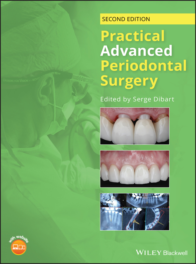
A fully updated second edition of this well-illustrated guide to advanced surgical procedures in periodontology Practical Advanced Periodontal Surgery, Second Edition is a step-by-step guide to cutting-edge surgical techniques and interdisciplinary treatment approaches in periodontology. Written by leading experts in the field, the book provides solutions to complex daily dental challenges with innovative approaches to each treatment modality. Procedures are described in a practical and accessible style, highlighting complex and advanced procedures using a highly illustrated visual format. This expanded edition includes three new chapters that cover IV sedation, digital technologies in clinical restorative dentistry, and advanced implant therapies in the esthetic zone post extraction. Well balanced and solidly grounded in the science, this reference work is an indispensable resource for the practitioner of advanced dentistry. This important guide: * Offers an easy-to-use, practical step-by-step format * Contains clinical photographs that detail the surgical procedures presented * Reviews the most advanced techniques in periodontal surgery and their integration with digital treatment planning and workflow * Discusses the pros and cons for each procedure, as well as limitations and potential complications * Features video clips illustrating key points in the procedures described on a companion website Written for periodontists, periodontal residents and general or restorative dentists, this revised edition of Practical Advanced Periodontal Surgery is a practical and complete clinical manual filled with illustrations for easy reference.
Sie lesen das E-Book in den Legimi-Apps auf:
Seitenzahl: 488
Veröffentlichungsjahr: 2020
Ähnliche


Table of Contents
Cover
List of Contributors
Acknowledgments
About the Companion Website
Introduction
Chapter 1: Conscious IV Sedation Utilizing Midazolam
INTRODUCTION
MIDAZOLAM (VERSED)
ARMAMENTARIUM
STEPS IN IV SEDATION
REFERENCES
Chapter 2: Bone Physiology and Metabolism
BONE COMPOSITION
BONE TYPES
BONE FORMATION
BONE DENSITY MEASURING TECHNIQUES
IMPLICATIONS FOR DENTAL TREATMENTS
REFERENCES
Chapter 3: Anatomy of the Dental/Alveolar
ANATOMIC REVIEW (EMPHASIS ON VASCULAR SUPPLY)
VASCULAR SUPPLY: MACRO AND MICRO
BLOOD SUPPLY WITHIN THE ALVEOLAR AND BASAL BONE OF THE DENTAL ARCHES
MICROARCHITECTURE OF THE BONE/TOOTH RELATIONSHIP AND THE INTERFACE OF SOFT AND HARD CONNECTIVE TISSUES
ANATOMY AND VASCULAR SUPPLY OF THE INVESTING SOFT CONNECTIVE TISSUES
CEMENTUM
ANTATOMY AND VASCULAR SUPPLY OF THE EPITHELIAL STRUCTURES
THE WOUND‐HEALING PROCESS
REFERENCES
Chapter 4: Piezocision
TM
Assisted Orthodontics in Everyday Practice
INTRODUCTION
THE TECHNIQUE
COMPUTER GUIDED PIEZOCISION ORTHODONTICS
DYNAMICALLY GUIDED PIEZOCISION
PIEZOCISION ASSISTED ORTHODONTICS WITH CLEAR ALIGNERS
INCORPORATING PIEZOCISION IN MULTIDISCIPLINARY TREATMENT
POST‐OPERATIVE CARE
CONTRAINDICATIONS FOR PIEZOCISION
POTENTIAL COMPLICATIONS
REFERENCES
Chapter 5: The Contribution of Periodontics to Endodontic Therapy
HISTORY AND EVOLUTION
TOOTH CONSERVATION VERSUS IMPLANTS
TREATMENT OF FAILED ROOT CANAL THERAPY
RATIONALE FOR ENDODONTIC SURGERY
INDICATIONS FOR ENDODONTIC SURGERY
CONTRAINDICATIONS FOR ENDODONTIC SURGERY
TYPES OF ENDODONTIC SURGERY
PERIRADICULAR SURGERY
PHASES OF APICOECTOMY AND SURGICAL TECHNIQUE
RECALL
REFERENCES
Chapter 6: The Contribution of Periodontics to Prosthodontics
INTRODUCTION
DIAGNOSTIC PHASE (DATA COLLECTION)
TREATMENT‐PLANNING PHASE
FINAL PROGNOSIS
CONCLUSION
REFERENCES
Chapter 7: The Contribution of Periodontics to the Correction of Vertical Alveolar Ridge Deficiencies
ALVEOLAR DISTRACTION OSTEOGENESIS SURGERY
REFERENCES
Chapter 8: Papillary Construction After Dental Implant Therapy
HISTORY
INDICATIONS
CONTRAINDICATIONS
ARMAMENTARIUM
TECHNIQUE
POSTOPERATIVE INSTRUCTIONS
SURGICAL INDEXING
POSSIBLE COMPLICATIONS
HEALING
REFERENCES
Chapter 9: Dental Implant Placement Including the Use of Short Implants
HISTORY
INDICATIONS
SURGICAL TECHNIQUE
IMPLANT PLACEMENT
SITE PREPARATION
THE FIXTURE (IMPLANT) INSTALLATION
POSSIBLE PROBLEMS AND COMPLICATIONS
REFERENCES
Chapter 10: Periodontal Medicine Including Biopsy Techniques
GINGIVAL NODULES
PARULIS
FIBROMA
PERIPHERAL OSSIFYING FIBROMA
PYOGENIC GRANULOMA
PERIPHERAL GIANT CELL GRANULOMA
DIAGNOSIS AND TREATMENT OF REACTIVE GINGIVAL NODULES
GINGIVAL CYST OF THE ADULT
MUCOCELE
DESQUAMATIVE GINGIVITIS
LICHEN PLANUS
PEMPHIGUS VULGARIS
MUCOUS MEMBRANE (CICATRICIAL) PEMPHIGOID
DIAGNOSIS AND TREATMENT OF DESQUAMATIVE GINGIVAL LESIONS
PLASMA CELL GINGIVITIS
ERYTHEMA MULTIFORME
GINGIVAL ENLARGEMENT
EPULIS FISSURATUM
MEDICATION‐INDUCED GINGIVAL OVERGROWTH
HYPERPLASTIC GINGIVITIS
LEUKEMIA
GINGIVAL FIBROMATOSIS
LIGNEOUS GINGIVITIS AND CONJUNCTIVITIS
WEGENER'S GRANULOMATOSIS
PIGMENTED LESIONS
PHYSIOLOGIC PIGMENTATION
MEDICATION‐INDUCED PIGMENTATION
SMOKER'S MELANOSIS
AMALGAM TATTOO
MELANOTIC MACULE
ORAL MELANOACANTHOMA (MELANOACANTHOSIS)
ORAL MELANOCYTIC NEVUS
ORAL MELANOMA
SANGUINARIA‐INDUCED LEUKOPLAKIA
PROLIFERATIVE VERRUCOUS LEUKOPLAKIA
MALIGNANT NEOPLASIA
SQUAMOUS CELL CARCINOMA
VERRUCOUS CARCINOMA
METASTATIC DISEASE
INFECTIONS
HERPES
HIV‐ASSOCIATED GINGIVITIS
ORAL SOFT TISSUE BIOPSY TECHNIQUES
ARMAMENTARIUM
INCISIONAL SCALPEL BIOPSY
EXCISIONAL SCALPEL BIOPSY
BIOPSY DATA SHEET
REFERENCES
Chapter 11: Sinus Augmentation Using Tissue‐Engineered Bone
HISTORY
INDICATIONS
CONTRAINDICATIONS
ARMAMENTARIUM
SINUS AUGMENTATION USING TISSUE‐ENGINEERED BONE DISCS
TRANSPLANT IMPLANTATION SURGERY (SINUS AUGMENTATION PROCEDURE USING TISSUE‐ENGINEERED BONE DISCS)
SINUS LIFT USING AUTOGENOUS MESENCHYMAL CELLS PROCESSED CHAIRSIDE
REFERENCES
Chapter 12: Extraction Site Management in the Esthetic Zone
INTRODUCTION
THE INFLUENCE OF TISSUE VOLUME ON THE PERI‐IMPLANT “PINK” ESTHETICS
TISSUE VOLUME AVAILABILITY AND REQUIREMENTS
PRE‐OPERATIVE IMPLANT SITE ASSESSMENT
TISSUE AUGMENTATION AT THE TIME OF TOOTH EXTRACTION
MANAGEMENT OF CLASS I SOCKETS
ARMAMENTARIUM
THREE‐DIMENSIONAL IMPLANT POSITIONING
SELECTION OF THE BONE GRAFT MATERIAL
RATIONALE
SOCKET SEAL
AUTOGENOUS TISSUE FOR CONCOMITANT BUCCAL VOLUME AUGMENTATION AND SOCKET SEAL PROCEDURES
SUB‐EPITHELIAL CONNECTIVE TISSUE GRAFT
COMPROMISED SOCKETS
FLAPLESS RIDGE PRESERVATION
Armamentarium
RIDGE PRESERVATION UTILIZING BARRIER MEMBRANES
ESTHETIC RIDGE AUGMENTATION
OPEN FLAP APPROACH FOR EXTRACTION SITE MANAGEMENT
SITE ANALYSIS AND CLASSIFICATION
SURGICAL PHASE
SUTURING OF THE GRAFT
STABILIZATION OF THE GRAFT
CLOSURE
MANAGING IMPLANT TISSUE DEFICIENCIES
CONCLUSION
REFERENCES
Chapter 13: Digital Technologies in Clinical Restorative Dentistry
FROM CONVENTIONAL TO DIGITAL TECHNOLOGIES
DIGITAL SOLUTIONS FOR PLANNING AND MANUFACTURING OF TEETH‐SUPPORTED RESTORATIONS
DIGITAL SOLUTIONS FOR PLANNING AND MANUFACTURING OF IMPLANT‐SUPPORTED RESTORATIONS
FUTURE PERSPECTIVES
ACKNOWLEDGMENTS
REFERENCES
Index
End User License Agreement
List of Tables
Chapter 1
Table 1.1 Continuum of sedation: definition and levels (2004).
Table 1.2 ASA physical status classification (American Society of Anesthesiol...
List of Illustrations
Chapter 1
Figure 1.1 Armamentarium needed to provide sedation: monitor, drug, IV sedat...
Figure 1.2 Pulse oximetry, oxygen cannula, blood pressure cuff.
Figure 1.3 Saline bag used for IV sedation.
Figure 1.4 IV catheters of various size.
Figure 1.5 Catheter insertion in the vein.
Figure 1.6 IV drip, monitoring the fluid that goes into the IV line.
Figure 1.7 IV portal secured with transparent film dressing.
Figure 1.8 Use the 1 ml Insulin Syringe to draw up 1 ml of 5 mg/ml midazolam...
Chapter 3
Figure 3.1 Distribution of the maxillary artery.
Figure 3.2 Palatal artery extension of greater palatine artery (black
arrow
)...
Figure 3.3 Maxillary sinus periosteum (Monkey/vascular‐India ink perfused). ...
Figure 3.4 Maxillary sinus periosteum (Monkey/vascular‐India ink perfused). ...
Figure 3.5 Normal dental/alveolar vascular supply. 1, Periosteal supply; 2, ...
Figure 3.6 Internal microarchitecture. (a) Maxillary bicuspid. (b) Mandibula...
Figure 3.7 Internal microarchitecture of furcation area of first molars. (a)...
Figure 3.8 Mature resting alveolar bone from core in human maxillary first m...
Figure 3.9 Small, India ink perfused vessels in very thin buccal plate (
arro
...
Figure 3.10 CT scan showing artery in buccal wall of sinus (
arrow
).
Figure 3.11 (Monkey) Arteriole wall merged with periosteum of antral wall ve...
Figure 3.12 Partial‐thickness flap at 14 days showing extensive arborization...
Figure 3.13 Disruption of vascular at mucogingival junction (MGJ) depends on...
Figure 3.14 Periosteum in attached gingival zone: dense Sharpey's fiber inse...
Figure 3.15 India ink perfused cleared specimen full‐thickness flap at seven...
Figure 3.16 Periosteum in mucosal zone: fibers run parallel to surface. Bone...
Figure 3.17 Large arteries and veins in mucosal area.
Figure 3.18
Mucogingival junction
(
MGJ
) transition from dense to areolar bas...
Figure 3.19
Mucogingival junction
(
MGJ
).
Figure 3.20 (a) Partial‐thickness flap. (b) Full‐thickness flap. No vessels ...
Figure 3.21 India ink–perfused specimen.
Figure 3.22 Capillary buds at four days begin to cross the incision line of ...
Figure 3.23 Fourteen days: regeneration of papillary loops. At this stage, n...
Figure 3.24 Twenty‐one–day regeneration of papillary loops: At this stage, w...
Chapter 4
Figure 4.1 Piezocision is done interproximally, making sure to decorticate p...
Figure 4.2 Once the interproximal decortication has been done, a tunneling p...
Figure 4.3 Bone grafting at time of Piezocision assisted orthodontics to str...
Figure 4.4 Prior to Piezocision assisted orthodontics.
Figure 4.5 Twelve months after starting Piezocision assisted orthodontics. N...
Figure 4.6 The incisions are planned digitally to avoid hitting the roots.
Figure 4.7 A surgical guide is being designed.
Figure 4.8 This is with the surgical guide in place.
Figure 4.9 The minimal opening provided by the surgical guide allows for pre...
Figure 4.10 The Piezocision is done and the surgical stent is removed.
Figure 4.11 Flared anterior teeth and multiple diastemas. Patient unhappy wi...
Figure 4.12 Lower anterior teeth impinging in the palate.
Figure 4.13 Super‐imposed before and after Clincheck showing projected teeth...
Figure 4.14 Piezocision on the maxilla and mandible is done after Clincheck ...
Figure 4.15 Finished treatment.
Figure 4.16 Patient has a better smile. The diastemas are closed and the tee...
Figure 4.17 Forty two year old female patient intra oral view (notice the di...
Figure 4.18 Occlusal view of maxilla showing mild crowding.
Figure 4.19 Occlusal view of mandible showing mild crowding.
Figure 4.20 The patient wears the aligners after the Piezocision procedure....
Figure 4.21 At the end of the orthodontic treatment. Treatment time was cut ...
Figure 4.22 Occlusal view of maxilla post treatment.
Figure 4.23 Occlusal view of the mandible post treatment.
Figure 4.24 The patient is ready to see the restorative specialist for venee...
Figure 4.25 Final restoration in place: porcelain laminate veneers (Prosthet...
Figure 4.26 The esthetic and functional concerns of the patient have been ad...
Chapter 5
Figure 5.1 Persistent inflammation associated with the mesial root of a mand...
Figure 5.2 Surgery reveals a hand file extending 3–4 mm beyond the root tip....
Figure 5.3 Instrument recovery, root resection, and retrograde obturation wi...
Figure 5.4 Persistent inflammation and symptoms associated with the mesial r...
Figure 5.5 Apicoectomy performed in conjunction with finding and obturation ...
Figure 5.6 A four‐year follow‐up shows complete healing.
Figure 5.7 Multiple sinus tracts trace to the location of the endodontic les...
Figure 5.8 An exploratory surgery and staining reveal a vertical root fractu...
Figure 5.9 Apicoectomy was performed on a “calcified” central incisor withou...
Figure 5.10 Nonsurgical root canal treatment was performed with the aid of t...
Figure 5.11 Osteotomy and stained resected root ends of a maxillary molar. N...
Figure 5.12 Failing apicoectomy and sinus tract tracing in a maxillary secon...
Figure 5.13 Conservative apicoectomy and obturation with MTA was performed d...
Figure 5.14 Five‐year recall revealed complete healing with no signs of the ...
Figure 5.15 Incision and drainage of an intraoral abscess. Note the latex dr...
Figure 5.16 Mandibular second molar exhibiting persistent radiolucency even ...
Figure 5.17 Tooth extraction without placing the forceps on root structure. ...
Figure 5.18 Tooth wrapped in sterile gauze and submerged in HBSS. Root resec...
Figure 5.19 White MTA retrofill.
Figure 5.20 Radiograph immediately post reimplantation.
Figure 5.21 Two‐year recall exhibits complete healing.
Figure 5.22 Sinus tract tracing and the location of the mid‐root radiolucenc...
Figure 5.23 Upon the reflection of the soft tissue flap, an isolated endodon...
Figure 5.24 Staining reveals a perforation on the mesial aspect of the root....
Figure 5.25 A three‐month recall revealed partial healing and no signs of th...
Figure 5.26 Maxillary first molar exhibiting persistent symptoms despite the...
Figure 5.27 Triangular full‐thickness flap provides access to the surgical s...
Figure 5.28 Apicoectomy and retrofill with MTA was performed on all three ro...
Figure 5.29 Submarginal incision and suturing with 6‐0 Vicryl sutures in the...
Figure 5.30 Suture removal four days later reveals great healing with minima...
Figure 5.31 Failing root canal treatment on maxillary first and second premo...
Figure 5.32 Flap elevation reveals fenestrations over the root prominences i...
Figure 5.33 Osteotomy is initiated by slow removal of the buccal cortical bo...
Figure 5.34 Endodontic lesion is enucleated in whole and the root tips are r...
Figure 5.35 One‐year follow‐up demonstrates complete healing of both teeth....
Figure 5.36 The resected and stained mesial root of a mandibular molar revea...
Figure 5.37 Mandibular first molar exhibiting persistent pathology of the me...
Figure 5.38 Apicoectomy, retropreparation, and retrofill of the MB and ML ca...
Figure 5.39 Near‐complete healing is noted at six‐month recall appointment....
Chapter 6
Figure 6.1 Numbering system used in this chapter.
Figure 6.2 Full‐face frontal view of patient.
Figure 6.3 Smile line.
Figure 6.4 Intraoral view.
Figure 6.5 Complete‐mouth radiographs.
Figure 6.6 Periodontal charting.
Figure 6.7 (a) Teeth Nos. 3, 5, and 6 after removal of defective restoration...
Figure 6.8 (a) Teeth Nos. 11, 12, and 13 after removal of defective restorat...
Figure 6.9 Provisional restorations, Nos. 3‐x‐5, 6, 11, 12, and 13. Note the...
Figure 6.10 Preprosthetic treatment plan: (a) Soft tissue augmentation, area...
Figure 6.11 (a and b) Soft tissue inlay graft site No. 4, preoperative view....
Figure 6.12 Surgical crown lengthening procedure tooth No. 13. (a) Preoperat...
Figure 6.13 Microsurgical crown‐lengthening procedure for the facial surface...
Figure 6.14 Wax replica of proposed treatment plan.
Figure 6.15 Preparations for veneers, Nos. 8 and 9.
Figure 6.16 Provisional restoration, Nos. 3‐x‐5‐6‐8‐9‐11‐12‐13. (a) After co...
Figure 6.17 (a) Gingival displacement cord in place. (b) Final impression wi...
Figure 6.18 Porcelain laminate veneers, Nos. 8 and 9, on cast (a) and bonded...
Figure 6.19 Two weeks after cementation of veneers, shade was selected (Vita...
Figure 6.20 (a) Final restorations after porcelain application and glazing. ...
Figure 6.21 Intraoral view of final restorations.
Figure 6.22 Postoperative view of the new smile line.
Figure 6.23 Before (a) and after (b) (full‐face view). Before (c) and after ...
Figure 6.24 Full‐face frontal view of patient.
Figure 6.25 Intraoral views. (a) MIP. (b) Maxillary arch. (c) Mandibular arc...
Figure 6.26 Complete‐mouth radiographs.
Figure 6.27 CT scan evaluation. (a) Panoramic cut. (b) Horizontal cut. (c) S...
Figure 6.28 Preprosthetic phase. Tooth No. 20 was extracted atraumatically. ...
Figure 6.29 Implants were uncovered four months later. (a) Right side. (b) L...
Figure 6.30 (a) Removal of defective FPD Nos. 22‐x‐x‐x‐x‐27‐28. (b) Horizont...
Figure 6.31 Cast post‐and‐core. (a) Try‐in. (b) Delivery.
Figure 6.32 Impression was made for fabrication of provisional restorations....
Figure 6.33 (a) Face‐bow transfer. (b) Casts mounted in centric relation.
Figure 6.34 Surgical mounts (a and b) of the dental implants were prepared t...
Figure 6.35 (a) Wax replica of the mandibular arch. (b) Heat processed provi...
Figure 6.36 Patient's smile after provisional restorations were placed.
Figure 6.37 (a) Final impression made with polyether impression material. (b...
Figure 6.38 (a) Jaw relation record at centric relation with Lucia jig (Luci...
Figure 6.39 (a and b) Clear vacuum‐formed shell of duplicate cast of patient...
Figure 6.40 (a) Metal castings and frameworks. (b) Metal try‐in. (c) Fit Che...
Figure 6.41 Restorations after porcelain application. (a) In occlusion. (b) ...
Figure 6.42 Canine guidance. (a) Right side. (b) Left side.
Figure 6.43 Clinical try‐in (a) and final delivery (b).
Figure 6.44 Intraoral view before (a) and after (b) treatment.
Figure 6.45 Patient's smile after treatment.
Figure 6.46 Full‐face frontal view of patient.
Figure 6.47 Intraoral view.
Figure 6.48 Complete‐mouth radiographs.
Figure 6.49 Periodontal charting.
Figure 6.50 Diagnostic casts.
Figure 6.51 Wax replica of tentative treatment plan.
Figure 6.52 (a and b) Defective fixed restorations were removed. Note the co...
Figure 6.53 Caries control and temporization, teeth Nos. 20 and 21. (a) Faci...
Figure 6.54 Intraoral views before (a) and after (b) provisional restoration...
Figure 6.55 Gingival line discrepancy.
Figure 6.56 Wax replica of finalized treatment plan for maxillary arch.
Figure 6.57 Wax replica of finalized treatment plan for mandibular arch.
Figure 6.58 Crown lengthening for the anterior sextant to gain crown length ...
Figure 6.59 Crown‐lengthening procedure for teeth Nos. 6–11. (a) Preoperativ...
Figure 6.60 Intraoral view before (a) and after (b) surgery. Smile before (c...
Figure 6.61 Crown‐lengthening procedure for teeth Nos. 20 and 21. (a) Preope...
Figure 6.62 Dual‐purpose template for implants Nos. 3, 4, and 5.
Figure 6.63 CT scan evaluation for the implants. (a) Panoramic cut. The segm...
Figure 6.64 Extraction of tooth No. 4. Note the Seibert's Class I ridge defe...
Figure 6.65 Sinus floor elevation and guided bone regeneration. (a) Lateral ...
Figure 6.66 CT scan evaluation after sinus floor elevation (a). Note the gai...
Figure 6.67 Implant placement sites Nos. 3, 4, and 5. (a) Full‐thickness fla...
Figure 6.68 Uncovering of implants. (a and b) Implants uncovered six months ...
Figure 6.69 Provisional restoration relined four weeks after uncovering. (a)...
Figure 6.70 Final impression of all teeth and implants. (a and b) Gingival d...
Figure 6.71 Face‐bow transfer (a) and centric jaw relation record (b and c) ...
Figure 6.72 Definitive casts mounted and cross‐mounted with the provisional ...
Figure 6.73 (a) Die relief placed on dies. (b) Acrylic resin artificial toot...
Figure 6.74 Putty index of the provisional restoration was made to provide a...
Figure 6.75 (a) Custom abutments were fabricated. (b and c) Verification jig...
Figure 6.76 (a) Try‐in of custom abutments. (b) Verification jig indicated t...
Figure 6.77 (a) Metal castings and frameworks were fabricated. (b) Castings ...
Figure 6.78 At the final try‐in appointment, new jaw relation records were m...
Figure 6.79 (a) Porcelain applied, Vita shade B1. (b) Restorations tried in ...
Figure 6.80 Intraoral views before (a) and after (b). Smile before (c) and a...
Chapter 7
Figure 7.1 Patient presenting with a vertical height defect subsequent to th...
Figure 7.2 Tooth No. 8 will be extracted due to severe periodontal disease. ...
Figure 7.3 The incision is high up in the vestibule to allow for flap mobili...
Figure 7.4 The full‐thickness flap is reflected using a periosteal elevator....
Figure 7.5 Reflection stops at the alveolar crest.
Figure 7.6 The segment to be distracted is delineated with a sterile No. 2 p...
Figure 7.7 The segment to be cut is drawn on the bone. Notice the divergence...
Figure 7.8 The distractor is modified to fit the clinical picture.
Figure 7.9 The distractor is placed, verifying the correct direction of the ...
Figure 7.10 One hole in each arm of the distractor is predrilled; this will ...
Figure 7.11 Using the oscillating microsaw (KLS Martin, Jacksonville, FL, US...
Figure 7.12 It is important to get as close as possible to the palatal/lingu...
Figure 7.13 A fine osseous chisel (or modified spatula) is used very careful...
Figure 7.14 The distractor is repositioned very accurately due to the previo...
Figure 7.15 The distractor is securely in place.
Figure 7.16 The distractor is activated to make sure that there will be no i...
Figure 7.17 After bringing back the segment to its original position, a smal...
Figure 7.18 A two‐layer suturing technique is used to close the wound. First...
Figure 7.19 Now that the deeper layers are sutured, the second layer will ap...
Figure 7.20 The temporary removable prosthesis is adjusted, so that it will ...
Figure 7.21 The patient with the adjusted prosthesis in place. The device is...
Figure 7.22 Periapical radiograph of the segment at the end of the alveolar ...
Figure 7.23 The bone has been distracted to the desired length. We ask the p...
Figure 7.24 Two months after the end of the distraction period, the device i...
Figure 7.25 The distractor is exposed by blunt dissection with a periosteal ...
Figure 7.26 The screws are removed, as well as the device. Notice the amount...
Figure 7.27 The surgical wound is closed with internal and external sutures,...
Figure 7.28 A 30‐year‐old patient presenting with a posterior vertical heigh...
Figure 7.29 An exact replica of the patient's mandible. This model (ClearVie...
Figure 7.30 Radiographic images (CT scan of the patient's mandible) showing ...
Figure 7.31 The segment to be distracted is drawn on the model and will be r...
Figure 7.32 The
arrow
shows an incorrect vector of distraction. The bony seg...
Figure 7.33 The
arrow
shows a correct vector of distraction. The bony segmen...
Chapter 8
Figure 8.1 Diagram showing the uncovering incision and procedures for a sing...
Figure 8.2 Diagram showing the uncovering incision and procedures for two im...
Figure 8.3 Before uncovering implant Nos. 4 and 5.
Figure 8.4 The abutment and provisional restorations for Nos. 4 and 5 in pla...
Figure 8.5 The palatal view. The U‐ and H‐shaped flaps have been folded, cre...
Figure 8.6 Two weeks postoperatively. The area has healed uneventfully.
Figure 8.7 Five months postoperatively. Notice the formation of the papilla ...
Figure 8.8 Five months postoperatively (palatal view). Notice the presence o...
Figure 8.9 Area with the final restorations at 20 months postoperatively.
Chapter 9
Figure 9.1 Image of a Branemark implant depicting design and surface structu...
Figure 9.2 (a) Branemark's prototype implant geometry. (b) Osteotomy outline...
Figure 9.3 Implant fitted into the osteotomy site (cylindrical shape) Thread...
Figure 9.4 Tapered implant and outline of osteotomy site without thread tapp...
Figure 9.5 Tapered implant within the osteotomy site.
Figure 9.6 Bicon short implant (5.7 × 6 mm) placed in the mandible (especial...
Figure 9.7 Dry skull and CT scan showing limiting anatomic features both int...
Figure 9.8 (a) Panoramic radiograph (distortion ±25%). (b) Periapical radiog...
Figure 9.9 Two radiographic techniques – same patient area: (a) Conventional...
Figure 9.10 Incision design buccally (a) and palatally (b) before the placem...
Figure 9.11 Full‐thickness flap reflected to the buccal, exposing alveolar c...
Figure 9.12 Using a pilot or round bur, future site of implant osteotomy is ...
Figure 9.13 Initial cylinder drill is used to initiate the osteotomy.
Figure 9.14 Directional guide used to check the proper alignment and 2 dimen...
Figure 9.15 (a) Directional guide shows the proper alignment of the implant ...
Figure 9.16 Internal architecture notches on buccal of crown. (a) Maxillary ...
Figure 9.17 Internal architecture of furcation area of first molars. (Notche...
Figure 9.18 The cover screw is used to seal the coronal portion of the impla...
Figure 9.19 (a) Cover screw is seated. (b) Implant is at level or below alve...
Figure 9.20 Mylohyoid insertion line (concavity below, submandibular gland) ...
Figure 9.21 Implant displaced into maxillary sinus. Student failed to sense ...
Figure 9.22 Diagram showing sublingual and submental arteries that can be in...
Figure 9.23 Anatomic limits. Sinus extension, resulting in less than 1 mm bo...
Figure 9.24 Periapical radiograph showing mandibular molar necessitating ext...
Figure 9.25 Short implants (Bicon, Boston, MA, USA) were placed to overcome ...
Figure 9.26 Periapical radiograph showing implants restored.
Figure 9.27 Clinical picture of restored short implants.
Figure 9.28 Short implants were used to overcome the anatomical limitations ...
Figure 9.29 Clinical picture of final implant‐supported restoration.
Chapter 10
Figure 10.1 Nodular erythematous mass of granulation tissue near the mucobuc...
Figure 10.2 Pink, smooth‐surfaced nodular mass of the mandibular attached gi...
Figure 10.3 Erythematous ulcerated mass of the palatal gingiva.
Figure 10.4 Erythematous nodular mass arising from the mandibular anterior g...
Figure 10.5 Ulcerated reddish‐purple mass of the mandibular anterior gingiva...
Figure 10.6 Fluid‐filled lesion in the mandibular premolar region of the att...
Figure 10.7 Bluish fluctuant swelling of the lower labial mucosa.
Figure 10.8 Erosive lichen planus presenting as desquamative gingivitis with...
Figure 10.9 Focal areas of painful erythematous marginal gingiva.
Figure 10.10 Erosive lesions affecting the anterior mandibular gingiva and m...
Figure 10.11 Desquamative gingival lesions representing the only affected si...
Figure 10.12 Diffuse, erythematous changes of the attached and free gingival...
Figure 10.13 Ulceration and crusting lesions involving the labial vermilion....
Figure 10.14 Redundant hyperplastic folds of tissue in the anterior maxillar...
Figure 10.15 Marked gingival hyperplasia in a patient using calcium channel ...
Figure 10.16 Diffuse enlargement and erythema of the marginal and papillary ...
Figure 10.17 Diffuse gingival enlargement and hemorrhage in this patient sub...
Figure 10.18 Band‐like pigmentation of the attached gingiva.
Figure 10.19 Pigmentation of the gingiva associated with use of minocycline....
Figure 10.20 Diffuse pigmentation of the anterior attached gingiva in a heav...
Figure 10.21 Multifocal areas of mucosal pigmentation at the apices of teeth...
Figure 10.22 Well‐demarcated brown macular lesion of the lower labial mucosa...
Figure 10.23 Smooth pigmented lesion of recent onset of the posterior buccal...
Figure 10.24 Slightly raised pigmented lesion of the posterior hard palate....
Figure 10.25 Irregular pigmented lesion of the posterior palate.
Figure 10.26 White plaque of the maxillary mucobuccal fold.
Figure 10.27 Exophytic erythroleukoplakic lesion of the anterior maxillary g...
Figure 10.28 Extensive exophytic white papillary lesion involving the edentu...
Figure 10.29 Metastatic melanoma to the anterior maxillary gingiva.
Figure 10.30 Multiple painful punctate areas of ulceration involving the max...
Figure 10.31 Excisional biopsy. Notice the angulation of the blade, which wi...
Figure 10.32 Elliptical incision to remove a growth located on the lower lip...
Figure 10.33 Biopsy container, the amount of liquid present should be suffic...
Figure 10.34 Biopsy data sheet used at Boston University School of Dental Me...
Chapter 11
Figure 11.1 Collection of a periosteal biopsy. Periosteal tissue was harvest...
Figure 11.2 Tissue‐engineered bone discs. (a) Discs were kept in transportat...
Figure 11.3 Sinus augmentation using tissue‐engineered bone discs. (a) A lat...
Figure 11.4 Radiographic evaluation of the grafted site. (a) A periapical ra...
Figure 11.5 Histological staining of core biopsy taken from the future impla...
Figure 11.6 Clinical view of the restored implant. (a and b) Implant was res...
Figure 11.7 Material taken from the bone marrow through aspiration.
Figure 11.8 The material is placed in the centrifuge and the plasma is separ...
Figure 11.9 The stem cell‐rich material is mixed with the xenograft (Bio‐Oss...
Figure 11.10 The graft mixture is loaded into the syringe.
Figure 11.11 The bone graft is delivered into the sinus with simultaneous im...
Figure 11.12 Four months later prior to uncovering.
Chapter 12
Figure 12.1 Triad of contemporary implant dentistry (Buser et al. 2017; Link...
Figure 12.2 : Pink and white esthetic score. (a) Mesial Papilla. (b) Distal ...
Figure 12.3 (a) Implant placement in an upper central incisor area. (b) Note...
Figure 12.4 (a) Buccal veneer grafting performed at the time of implant plac...
Figure 12.5 (a and b) Robust buccal volume augmentation following combined c...
Figure 12.6 (a) Clinical situation following bone and soft tissue augmentati...
Figure 12.7 Tissue thickness augmentation following connective tissue grafti...
Figure 12.8 Close up view of the buccal plate of a canine socket following e...
Figure 12.9 Schematic illustrating the differences between the peri‐implant ...
Figure 12.10 (a–d) Pre‐operative assessment of the interproximal height of b...
Figure 12.11 (a) Pre‐operative bone sounding of the buccal plate reveals pro...
Figure 12.12 Tooth angulation in relation to the alveolar housing. Class I: ...
Figure 12.13 (a–e) Immediate implant placement performed following extractio...
Figure 12.14 Clinical example of immediate implant placement in a class II e...
Figure 12.15 Clinical example of Class II socket. Severe compromise of the b...
Figure 12.16 (a and b) Separation of the supra‐crestal fibers with a micro‐b...
Figure 12.17 (a and b) Long shanked diamond needle bur is utilized initiate ...
Figure 12.18 Socket degranulation may be performed by spoon currettes. N.B. ...
Figure 12.19 Correct implant positioning should be assessed during implant p...
Figure 12.20 Intra‐operative view of an immediate implant position in relati...
Figure 12.21 In class I (Kan) sockets, placing implants in the space occupie...
Figure 12.22 Mesio‐distal positioning of implant placement in the esthetic z...
Figure 12.23 Implant depth can be measured utilizing different clinical indi...
Figure 12.24 From left to right columns: (a–c) Atraumatic extraction of uppe...
Figure 12.25 Five months follow‐up of both volume and soft tissue scalloped ...
Figure 12.26 In the absence of a buccal plate or in severely compromised per...
Figure 12.27 (a–d) Immediate implant placement was combined with bone grafti...
Figure 12.28 From left to right. Suture entry point: The needle is advanced ...
Figure 12.29 Necrosis or delayed vascularization of the exposed portion of t...
Figure 12.30 Following harvesting of a FGG, the edges of the graft that will...
Figure 12.31 Immediate implant placement with connective tissue grafting aug...
Figure 12.32 Graft orientation may be horizontal or vertical depending on th...
Figure 12.33 (a) Atraumatic extraction of the lateral incisor. (b) The bucca...
Figure 12.34 Apical guiding suture for introduction of the connective tissue...
Figure 12.35 From left to right, step by step procedure for the apical guidi...
Figure 12.36 Two positioning mattress sutures are utilized to precisely posi...
Figure 12.37 (a) Palatal placement. (b) Connective tissue graft placement an...
Figure 12.38 Flapless Ridge preservation.
Figure 12.39 Flapless ridge preservation membrane insertion.
Figure 12.40 Outline of the membrane placement underneath the prepared tunne...
Figure 12.41 Sub‐optimal implant placement correction. (a) Note the excessiv...
Figure 12.42 Flapless ridge preservation and implant replacement.
Figure 12.43 Esthetic Ridge Augmentation with growth factor induced bone mat...
Figure 12.44 Simultaneous soft tissue grafting with ridge augmentation in se...
Figure 12.45 Left column top: Dehisence defects with different severity leve...
Figure 12.46 (a) CT scan with digital wax‐up and virtual implant placement e...
Figure 12.47 The diagnostic wax‐up is then converted into a surgical guide t...
Figure 12.48 Example of membrane fixation with tacks placed to stabilize one...
Figure 12.49 (a–d) (a) Frontal view implant placement, guided bone regenerat...
Figure 12.50 (a–c) Incorrect choice of suture material and placement compres...
Figure 12.51 Immediate implant placement with horizontal ridge augmentation ...
Figure 12.52 (a–c) A mattress suture is used to anchor the graft to the flap...
Figure 12.53 (a–c) Extraction and implant preparation osteotomies. (d) Membr...
Figure 12.54 Class IV type sockets with inadequate socket or apical topograp...
Figure 12.55 Note the bone preservation of the ridge with maintanence of the...
Figure 12.56 Soft tissue punch performed for flapless implant placement. Not...
Figure 12.57 Implant placement and guided bone regeneration performed throug...
Figure 12.58 Final implant restoration and veneers to mask the congenitally ...
Figure 12.59 (a–j) Sequential procedures for the treatment of a failed impla...
Figure 12.60 Sequential procedures for the treatment of an implant dehiscenc...
Figure 12.61 Fundamentals of tissue engineering and regeneration.
Chapter 13
Figure 13.1 Adapted from technology adoption life cycle.
Figure 13.2.1 Rotational calibration of the face photo based on the facial h...
Figure 13.2.2 Photos of retracted and non‐retracted smile are calibrated by ...
Figure 13.2.3 Calibration of the dimensions is done with the ruler, in order...
Figure 13.2.4 Esthetic framework has been determined from the frontal, 12 o'...
Figure 13.2.5 Different teeth form libraries can be employed to facilitate t...
Figure 13.2.6 Planned smile design of upper anterior teeth with calibrated m...
Figure 13.2.7 Lower jaw tracking device (a) can be used with CBCT data, allo...
Figure 13.2.8 Restorative treatment for upper incisors (a) was planned using...
Figure 13.2.9 Patient with worn dentition had esthetic demands (a), therefor...
Figure 13.2.10 CAD software offers many useful tools to control the design o...
Figure 13.2.11 Hybrid conventional‐digital method was utilized to restore up...
Figure 13.2.12 Tooth‐ and implant‐supported removable partial denture and zi...
Figure 13.3.1 Initial clinical situation resulting from previous dental trau...
Figure 13.3.2 Custom abutment and temporary cement‐retained crown is designe...
Figure 13.3.3 A two implant placement was planned as a fully‐guided procedur...
Figure 13.3.4 Implant was planned in the site of missing molar tooth (a). Ri...
Figure 13.3.5 Full‐arch implant‐supported fixed prostheses were planned for ...
Figure 13.4 Kapanu AR application (Ivoclar Vivadent) allows visualization of...
Guide
Cover
Table of Contents
Begin Reading
Pages
iii
iv
v
xi
xii
xiii
xv
1
3
4
5
6
7
8
9
11
12
13
14
15
16
17
19
20
21
22
23
24
25
26
27
28
29
30
31
32
33
35
36
37
38
39
40
41
42
43
44
45
46
47
48
49
50
51
52
53
54
55
56
57
58
59
60
61
62
63
64
65
66
67
68
69
70
71
72
73
74
75
76
77
78
79
80
81
82
83
84
85
86
87
88
89
90
91
92
93
94
95
96
97
98
99
100
101
102
103
104
105
107
108
109
110
111
112
113
114
115
117
118
119
120
121
122
123
124
125
126
127
128
129
130
131
132
133
134
135
137
138
139
140
141
142
143
144
145
146
147
148
149
150
151
152
153
154
155
156
157
158
159
160
161
162
163
164
165
166
167
168
169
170
171
172
173
174
175
176
177
178
179
180
181
182
183
184
185
186
187
188
189
190
191
192
193
194
195
196
197
198
199
200
201
202
203
204
205
206
207
208
209
210
211
212
213
214
215
216
217
218
219
220
221
222
223
224
225
226
227
228
229
230
231
232
233
234
235
236
237
PRACTICAL ADVANCED PERIODONTAL SURGERY
Second Edition
Edited by
Serge Dibart, DMD
Professor and ChairDepartment of PeriodontologyDirector Advanced Specialty Program in PeriodonticsBoston University Henry M. Goldman School of Dental MedicineBoston, MA, USA
This edition first published 2020© 2020 John Wiley & Sons, Inc.
Edition HistoryBlackwell Munksgaard (1e, 2007)
All rights reserved. No part of this publication may be reproduced, stored in a retrieval system, or transmitted, in any form or by any means, electronic, mechanical, photocopying, recording or otherwise, except as permitted by law. Advice on how to obtain permission to reuse material from this title is available at http://www.wiley.com/go/permissions.
The right of Serge Dibart to be identified as the author of the editorial material in this work has been asserted in accordance with law.
Registered Office(s)John Wiley & Sons, Inc., 111 River Street, Hoboken, NJ 07030, USAJohn Wiley & Sons Ltd, The Atrium, Southern Gate, Chichester, West Sussex, PO19 8SQ, UKWiley‐VCH Verlag GmbH & Co. KGaA, Boschstr. 12, 69469 Weinheim, GermanyJohn Wiley & Sons Singapore Pte. Ltd, 1 Fusionopolis Walk, #07‐01 Solaris South Tower, Singapore 138628
Editorial Office111 River Street, Hoboken, NJ 07030, USA
For details of our global editorial offices, customer services, and more information about Wiley products visit us at www.wiley.com.
Wiley also publishes its books in a variety of electronic formats and by print‐on‐demand. Some content that appears in standard print versions of this book may not be available in other formats.
Limit of Liability/Disclaimer of WarrantyThe contents of this work are intended to further general scientific research, understanding, and discussion only and are not intended and should not be relied upon as recommending or promoting scientific method, diagnosis, or treatment by physicians for any particular patient. In view of ongoing research, equipment modifications, changes in governmental regulations, and the constant flow of information relating to the use of medicines, equipment, and devices, the reader is urged to review and evaluate the information provided in the package insert or instructions for each medicine, equipment, or device for, among other things, any changes in the instructions or indication of usage and for added warnings and precautions. While the publisher and authors have used their best efforts in preparing this work, they make no representations or warranties with respect to the accuracy or completeness of the contents of this work and specifically disclaim all warranties, including without limitation any implied warranties of merchantability or fitness for a particular purpose. No warranty may be created or extended by sales representatives, written sales materials or promotional statements for this work. The fact that an organization, website, or product is referred to in this work as a citation and/or potential source of further information does not mean that the publisher and authors endorse the information or services the organization, website, or product may provide or recommendations it may make. This work is sold with the understanding that the publisher is not engaged in rendering professional services. The advice and strategies contained herein may not be suitable for your situation. You should consult with a specialist where appropriate. Further, readers should be aware that websites listed in this work may have changed or disappeared between when this work was written and when it is read. Neither the publisher nor authors shall be liable for any loss of profit or any other commercial damages, including but not limited to special, incidental, consequential, or other damages.
Library of Congress Cataloging‐in‐Publication Data
Names: Dibart, Serge, editor.Title: Practical advanced periodontal surgery / edited by Serge Dibart.Description: 2 edition. | Hoboken, NJ : Wiley‐Blackwell, 2020. | Includes bibliographical references and index.Identifiers: LCCN 2019046551 (print) | LCCN 2019046552 (ebook) | ISBN 9781119196310 (hardback) | ISBN 9781119196334 (adobe PDF) | ISBN 9781119196341 (epub)Subjects: MESH: Periodontium–surgery | Oral Surgical Procedures,Preprosthetic–methods | Periodontics–methods | Atlas Classification: LCC RK361 (print) | LCC RK361 (ebook) | NLM WU 317 | DDC 617.6/32–dc23LC record available at https://lccn.loc.gov/2019046551LC ebook record available at https://lccn.loc.gov/2019046552
Cover Design: WileyCover Image: Courtesy of Serge Dibart
Ziedonis (Zie) Skobe, PhD
29 April 1941–5 August 2018
Known as a “gentle giant” who had “a remarkable life and career,” Zie guided and supported hundreds of projects and grants, and countless young scientists, during his 40 plus years career at the former Forsyth Dental Institute.
Always proud of his immigrant background, he arrived in the USA from Latvia as a refugee during World War II, overcoming language barriers while learning English then working in the construction industry as a laborer while studying for his PhD
Throughout his long career, he always had a welcoming smile and encouraging words for the young scientists whom he mentored. His early experience with learning English prepared him to enthusiastically help those for whom English was not a first language. He is remembered by all those whose lives he touched for being a great friend, scientist, and mentor with a kind and generous heart. You will not be forgotten, Zie. Rest In Peace.
List of Contributors
Nawaf J. Al‐Dousari, DDS, MSDPractice Limited to ProsthodonticsArmed Forces HospitalMinistry of DefenseShamiya, Kuwait City, Kuwait
Haneen N. Bokhadoor, DDS, MSDPractice Limited to Periodontics and Dental ImplantsBneid Al Gar Specialty Dental CenterMinistry of HealthShamiya, Kuwait City, Kuwait
Rokas Borusevicˇius, DDSDivision of Periodontology, Institute of OdontologyFaculty of MedicineVilnius University, Vilnius, Lithuania
Jean‐Pierre Dibart, MDRheumatology and Sport MedicineMarseilles, France
Serge Dibart, DMDProfessor and ChairDepartment of PeriodontologyDirector Advanced Specialty Program in PeriodonticsBoston University Henry M. Goldman School of Dental MedicineBoston, MA, USA
Thomas Van Dyke, DDS, PhDVice President and Senior Member of StaffForsyth InstituteProfessor of Oral Medicine, Infection and ImmunityFaculty of Medicine, Harvard UniversityBoston, MA, USA
Agne&c.dotab; Gecˇiauskaite&c.dotab;, DDSDivision of Prosthodontics, Institute of Odontology, Faculty of MedicineVilnius University, Vilnius, Lithuania
Sadru Kabani, DMD, MSCo‐Director of Oral PathologySTRATADXLexington, MA, USA
Elif Keser, DDS, PhDPrivate Practice, London, UKAdjunct Assistant Professor, Department of Orthodontics & Dentofacial OrthopedicsBoston University Henry M. Goldman School of Dental MedicineBoston, MA, USA
Jess Liu, DDS, MSDClinical Assistant ProfessorDepartment of PeriodontologyBoston University School of Dental MedicineBoston, MA, USA
Lorenzo Montesani, DDSPractice Limited to Prosthodontics and Implant DentistryRome, Italy
Luigi Montesani, MD, DDSPractice Limited to Periodontology, Prosthodontics, and Implant DentistryRome, Italy
Steven Morgano, DMDProfessor and ChairDepartment of Restorative DentistryRutgers University School of Dental MedicineNewark, NJ, USA
Mani Moulazadeh, DMDAssistant Clinical ProfessorDepartment of EndodonticsBoston University School of Dental MedicineBoston, MA, USA
Donald Nelson, DMDAssistant Clinical ProfessorDepartment of OrthodonticsHarvard School of Dental MedicineBoston, MA, USA
Vikki Noonan, DMD, DMScDirector and Associate Professor, Division of Oral PathologyBoston University Henry M. Goldman School of Dental MedicineBoston, MA, USA
Justinas Pletkus, DDSDivision of Prosthodontics, Institute of Odontology Faculty of MedicineVilnius University, Vilnius, Lithuania
Albert Price, DMD, MSClinical ProfessorDepartment of Periodontology and Oral BiologyBoston University School of Dental MedicineBoston, MA, USA
Vygandas Rutkūnas, DDS, PhDAssociate ProfessorDivision of Prosthodontics, Institute of Odontology Faculty of MedicineVilnius University, Vilnius, LithuaniaProDentum Clinic, Vilnius, Lithuania
Sherif Said, DDS, MSDClinical Assistant ProfessorDepartment of PeriodontologyBoston University School of Dental MedicineBoston, MA, USA
Ulrike Schulze‐Späte, DMD, PhDDiplomate, American Board of PeriodontologyDirector, Section of GeriodonticsDepartment of Conservative Dentistry and PeriodontologyCenter of Dental MedicineUniversity Hospital JenaJena, Germany
Peyman Shahidi, DDS, MScDPractice Limited to Periodontology and Implant DentistryToronto, Ontario, Canada
Ming Fang Su, DMD, MSClinical ProfessorDepartment of Periodontology and Oral BiologyBoston University School of Dental MedicineBoston, MA, USA
Yun Po Zhang, PhD, DDS(hon)DirectorClinical Dental ResearchColgate‐Palmolive CompanyPiscataway, NJ, USA
Acknowledgments
I would like to thank my colleagues and students of Boston University Henry M. School of Dental Medicine for their invaluable help. I would also like to thank Ms. Leila Joy Rosenthal for drawing Figures 7.32 and 7.33, Dr. Alessia De Vit Dr. Trevor Fujinaka for the video on Piezocision and Dr. Galip Gurel.
I would also like to thank Ms. Samantha Rose Burke for her invaluable help in formatting this manuscript, Mary Malin for copyediting and to the team at Wiley for bringing the book to Production.
About the Companion Website
This book is accompanied by a companion website:
www.wiley.com/go/dibart/advanced
The website includes 2 videos from Chapter 4.
Introduction
Thomas Van Dyke
As reflected in this Second Edition, the surgical techniques that span the scope of dentistry have continued to evolve. Predictable implant placement and bone augmentation techniques have become a common part of the repertoire of the periodontist. Importantly, these technical developments and the research on which they are based have impacted other specialties, including orthodontics, endodontics, oral and maxillofacial surgery, and prosthodontics.
In Practical Advanced Periodontal Surgery, Second Edition, Dr. Serge Dibart has updated, expanded, and improved on the landmark First Edition with a team of experts who have played a major role in the development of these concepts, in some cases, and their implementation, in all cases. It is arranged into 13 chapters that range from a review of the science leading up to new technologies to their implementation and the evidence backing their veracity. The contribution of periodontal concepts to orthodontics and endodontics is just an example of how modern periodontology adds to the armamentarium of all aspects of the dental profession.
The focus of this book is bone – the biology of bone and how an understanding of the basic principles of biology can be used to enhance treatment. The book begins with a review of bone biology and current understanding of wound healing. The discovery that surgically injured bone becomes rapidly osteopenic followed by increased turnover has been updated to include new clinical techniques for rapid tooth movement through Piezocision.
Notably, there are three new chapters in the Second Edition. The topics are vital to modern practice, including IV sedation by Dr. Jess Liu, Digital Technologies in Clinical Restorative Dentistry by Dr. Vygandas Rutkūnas and colleagues, and Extraction Site Management in the Esthetic Zone: Hard and Soft Tissue Reconstruction by Dr. Sherif Said. The final five chapters of the book are devoted to exploring the specialized needs of complex cases. The problems of inadequate vertical bone height and soft tissue defects can now be predictably addressed in most cases. In particular, the esthetic issues of lack of papillary redevelopment between adjacent implants are addressed by established investigators in the field. Distraction osteogenesis and papilla regeneration techniques now provide a means to enhance the esthetics of the most complicated cases.
Periodontal medicine has its roots in oral pathology/oral medicine. The forefathers of periodontics, physicians such as Gottlieb, Orban, and Goldman, were oral pathologists first. No book of advanced periodontal techniques would be complete without a review of the most common oral lesions that face the periodontist and their treatment, along with proper biopsy techniques.
The look to the future has also changed between the First and Second Editions. The future of periodontology is bright; we are provided an exciting glimpse of what is next.
Dr. Dibart has again brought together the subject, the team, and the expertise to produce a most valuable compilation of advanced techniques of modern periodontics. The content is based in science and is well‐balanced, providing a reference work and guide for the practitioner of advanced dentistry.
Chapter 1Conscious IV Sedation Utilizing Midazolam
Jess Liu
INTRODUCTION
Dental fear and anxiety are the common reasons why patients avoid seeking proper dental care. A survey conducted in the US has reported up to 30.5% of both US adults and adolescents experience a moderate to high dental fear (Gatchel 1989). Therefore, it is important for dentists to understand the management of dental fear and anxiety as an integral component of the overall treatment.
As defined by the American Society of Anesthesiologists (see Table 1.1), the continuums of depth of sedation are:
Minimal Sedation: Normal response to verbal stimulation.
Moderate Sedation: Purposeful response to verbal or tactile stimulation.
Deep Sedation: Purposeful response following repeated or painful stimulation.
General Anesthesia: Unarousable even with painful stimulus.
According to the American Society of Anesthesiologists moderate sedation is also known as “Conscious Sedation,” and by definition, conscious sedation is “a drug‐induced depression of consciousness during which patients respond purposefully to verbal commands, either alone or accompanied by light tactile stimulation. No interventions are required to maintain a patent airway, and spontaneous ventilation is adequate. Cardiovascular function is usually maintained.”
Conscious sedation can be achieved by different routes of administration such as enteral or parenteral administration. For the purpose of this chapter, parenteral administration of conscious sedation limited to intravenous administration of Midazolam (Versed) will be reviewed.
Training in Intravenous Conscious Sedation
While IV conscious sedation is relatively safe to practice, only a qualified and well‐trained healthcare provider who is able to manage emergency complications should perform the practice. Dentists who practice IV conscious sedation are mandated by all states to be certified by an approved continuing education program. Furthermore, each state is governed by its own rules and regulations for the administration of conscious sedation, therefore it is important to verify with the individual state dental board for the proper requirements to obtain a permit to practice IV conscious sedation.
MIDAZOLAM (VERSED)
Midazolam is a water soluble, short acting benzodiazepine central nervous system (CNS) depressant. Pharmacologically, it produces anxiolytic, hypnotic, anterograde amnestic, muscle relaxation, and anticonvulsant effects (Reves et al. 1985). Metabolized in the liver by cytochrome P450 enzymes, its mechanism of action is through binding of the GABAA receptors, (causing an influx of chloride ion which causes hyperpolarization of the neuron's membrane potential) creating a neural inhibition effect.
The onset of intravenous administration of midazolam is relatively fast with a short acting duration. Intravenous administration of 5 mg of midazolam in healthy adults has shown to take effect one to two minutes after administration and has a half‐life of approximately one to three hours (Smith et al. 1981).
It is important to understand that the use of midazolam is to produce conscious sedative effects and does not replace the need for proper local anesthesia. Therefore proper anesthetic should be administered prior to the starting of the dental procedure.
Table 1.1 Continuum of sedation: definition and levels (2004).
Continuum of depth of sedation: definition of general anesthesia and levels of sedation/analgesia
Minimal sedation (Anxiolysis)
Moderate sedation/analgesia (Conscious sedation)
Deep sedation/Analgesia
General anesthesia
Responsiveness
Normal response to verbal stimulation
Purposeful
a
response to verbal stimulation
Purposeful
a
response following repeated or painful stimulation
Unarousable even with painful stimulus
Airway
Unaffected
No intervention required
Intervention may be required
Intervention often required
Spontaneous Ventilation
Unaffected
Adequate
May be inadequate
Frequently inadequate
Cardiovascular Function
Unaffected
Usually maintained
Usually maintained
May be impaired
a Reflex withdrawal from a painful stimulus is NOT considered a purposeful response.
ARMAMENTARIUM
Monitoring equipment for:
Non‐invasive Blood Pressure
(
NIBP
)
Electrocardiogram (EKG)
Pulse Oximetry
Capnography
IV Supplies:
0.9% Sodium Chloride Injection 250 ml bag
Primary IV set (100″)
22 Gauge × 1″ Introcan Safety
®
IV Catheter
24 Gauge × ¾″ Introcan Safety IV Catheter
Basic Supplies:
1 ml Insulin Syringe
Blunt Plastic Cannula
Nasal Cannula
Supplemental Oxygen
1″ Latex free Tourniquet
3M Tegaderm Film Transparent Film Dressing
3M Transpore Tape
Gauze
Band‐Aids
Alcohol Wipes
Basic Medications:
Midazolam 5 mg/1 cc
Flumazenil 5 cc
ACLS Emergency Medical Kit (HealthFirst)
Please see Figure 1.1.
STEPS IN IV SEDATION
Patient pre‐op evaluation: As with all dental procedures, a thorough review of the patient's medical history is essential to ensure safe and successful treatment. Review of the patient's medical history with complete review of the system, current medications, as well as drug allergies will provide you the necessary information to assess the patient utilizing the ASA Physical Status Classification System (see Table 1.2). The authors recommend limiting the administration of conscious sedation with patients with ASA Physical status of 2 or less to reduce the chance of medical emergencies.
Contraindication:
Hypersensitivity
Acute narrow‐angle glaucoma
Hypotension
Pregnancy
Renal disease
Critically ill patients
Pre‐op instructions
No food or drinks eight hours prior to procedure.
Please wear comfortable loose‐fitting clothing with short sleeves to allow for monitoring of your blood pressure.
Must be accompanied by a person of legal age to escort you home.
No sedatives for 24 hours before appointment.
Day of Procedure:
Seat the patient
Review medical history.
If patient has medical history of asthma instruct patient to take two puffs of asthma inhaler prior to starting of procedure
.
Figure 1.1 Armamentarium needed to provide sedation: monitor, drug, IV sedation set.
Table 1.2 ASA physical status classification (American Society of Anesthesiologists 2015).
ASA physical status classification system
ASA Physical Status 1
A normal healthy patient
ASA Physical Status 2
A patient with mild systemic disease
ASA Physical Status 3
A patient with severe systemic disease
ASA Physical Status 4
A patient with severe systemic disease that is a constant threat to life
ASA Physical Status 5
A moribund patient who is not expected to survive without the operation
ASA Physical Status 6
A declared brain‐dead patient whose organs are being removed for donor purposes
Figure 1.2 Pulse oximetry, oxygen cannula, blood pressure cuff.
Attach patient monitors (See
Figure 1.2
) for:
Blood pressure
Electrocardiography (EKG)
Pulse oximetry (Oxygen saturation)
Capnography (CO2 partial pressure) Give earliest warning of respiratory distress
Record pre‐operatory vital signs: Blood pressure, pulse, respiratory rate, oxygen saturation, end tidal CO
2
level. If vital signs not within normal range re‐evaluate patient for the procedure.
Pre‐operative vital signs chart
Diagnosis
Systolic (mm Hg)
Diastolic (mm Hg)
Normal
Less than 120 and
Less than 80
Prehypertension
120–139 or
80–89
Hypertension Stage 1
140–159 or
90–99
Hypertension Stage 2
160 or higher or
100 or higher
Average range
Pulse Rate
Adult 60–80 beats/min
Respiratory Rate
12–20 breaths/min
Oxygen Saturation
95–100%
End tidal CO
2
35–45 mm Hg
Starting of IV:
Complete assemble of Primary IV infusion set with 0.9% Sodium Chloride Injection bag See
Figure 1.3
.
Exam and select visible superficial vein for venepuncture: Location: Dorsum of hand/wrist, Ventral Forearm, or Antecubital Fossa.
Contraindication for venepuncture site are:
Mastectomy
Cannulas
Scarring
Vein with valves or bifurcations
Figure 1.3 Saline bag used for IV sedation.
Methods of venous distension to facilitate venepuncture.
Application of tourniquet 3–4 in. above collection area with appropriate compression
Opening and closing of hand
Hanging of the arm below heart
Light slapping or rubbing of the area with alcohol wipe
Select appropriate Introcan Safety I.V. Catheter
(22/24 gauge is recommended). See Figures
1.4
and
1.5
.
Disinfect selected area of venepuncture with 70% isopropyl alcohol wipe
Insertion of needle and observe for blood return in the flashback chamber
Caution: At no time should venepuncture be performed on an artery
Remove tourniquet
Attach infusion set to catheter adaptor
Start IV drip, constant drip should be observed. See
Figure 1.6
.
Figure 1.4 IV catheters of various size.
Caution: Initially exam the area of venepuncture after starting IV drip for swelling to ensure proper venepuncture has been performed
Stabilize the catheter with 3M Tegaderm Film Transparent Film Dressing and 3M Transpore Tape. See
Figure 1.7
.
Dosage and Administration
Use the 1 ml Insulin Syringe U‐100 to draw up 1 ml of 5 mg/ml midazolam. See
Figure 1.8
.
Dosage and administration indicated for the intravenous administration of midazolam as provided by pharmaceutical company Hospira Inc. is as follows:
Healthy Adults Below the Age of 60:
Titrate slowly to the desired effect (e.g. the initiation of slurred speech). Some patients may respond to as little as 1 mg. No more than 2.5 mg should be given over a period of at least two minutes. Wait an additional two or more minutes to fully evaluate the sedative effect. If further titration is necessary, continue to titrate, using small increments, to the appropriate level of sedation. Wait an additional two or more minutes after each increment to fully evaluate the sedative effect. A total dose greater than 5 mg is not usually necessary to reach the desired endpoint.
Patients Age 60 or Older, and Debilitated or Chronically Ill Patients:
Because the danger of hypoventilation, airway obstruction, or apnea is greater in elderly patients and those with chronic disease states or decreased pulmonary reserve, and because the peak effect may take longer in these patients, increments should be smaller and the rate of injection slower. Titrate slowly to the desired effect (e.g. the initiation of slurred speech). Some patients may respond to as little as 1 mg. No more than 1.5 mg should be given over a period of no less than two minutes. Wait an additional two or more minutes to fully evaluate the sedative effect. If additional titration is necessary, it should be given at a rate of no more than 1 mg over a period of two minutes, waiting an additional two or more minutes each time to fully evaluate the sedative effect. Total doses greater than 3.5 mg are not usually necessary. If concomitant CNS depressant premedications are used in these patients, they will require at least 50% less midazolam than healthy young unpremedicated patients.
Figure 1.5 Catheter insertion in the vein.
Figure 1.6 IV drip, monitoring the fluid that goes into the IV line.
Figure 1.7 IV portal secured with transparent film dressing.
Starting of procedure is initiated with administering of appropriate local anesthesia after desired sedative effect is achieved.
Maintenance Dose:
Additional doses to maintain the desired level of sedation may be given in increments of 25% of the dose used to first reach the sedative endpoint, but again only by slow titration, especially in the elderly and chronically ill or debilitated patient. These additional doses should be given only after a thorough clinical evaluation clearly indicates the need for additional sedation. For conscious sedation in diagnostic or surgical interventions carried out under local anesthesia (Hospira, Inc., Midazolam Injection
2010
).
Upon completion of the procedure, stop the flow of the IV infusion followed by the removal of the IV catheter. Place sterile gauze over site of venepuncture and apply firm pressure for three to five minutes to prevent hematoma.
Figure 1.8 Use the 1 ml Insulin Syringe to draw up 1 ml of 5 mg/ml midazolam.
Escort patient to recovery room and continue to monitor patient's vital signs, once recovered release patient to escort.
Post‐operative instructions:
No sedatives 12 hours after procedure.
No consumption of alcoholic beverages after procedure.
No stairs without assistance or heavy lifting until completely recovered.
Do not drive, operate heavy machinery, or do any dangerous activities for the rest of the day.
Do not make important decisions for 24 hours after your appointment.
Drink lots of water for at least 12 hours after your appointment.
Reversal agent for midazolam:
In a situation when a patient is oversedated and does not respond purposefully to verbal commands. The reversal agent for benzodiazepine, flumazenil (Romazicon) can be administered. It reverses the effects of benzodiazepines by competitive inhibition at the benzodiazepine binding site on the GABAA receptor. The initial dose of 0.2 mg of flumazenil can be administered and takes about 2–2.5 minutes to take effect.
Initial dose: 0.2 mg IV one time over 30 seconds.
Repeated doses: 0.5 mg may be given every minute.
Maximum total dose 3 mg. Patients responding partially at 3 mg may receive additional doses up to 5 mg.
Most patients respond to 1–3 mg.
Resedation doses: 0.5 mg every 20 minutes to a total of 1 mg/dose and 3 mg/hour.


