18,49 €
Mehr erfahren.
- Herausgeber: The Crowood Press
- Kategorie: Lebensstil
- Sprache: Englisch
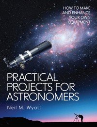
Astronomy and astrophotography are fascinating hobbies. It is possible to create and enhance astronomical equipment and accessories using techniques and materials accessible to the hobbyist metalworker or model engineer. Written by an amateur astronomer and experienced hobby engineer, this wide-ranging book presents tried and tested ideas from the simplest of gadgets to advanced projects. Includes how to design and make refracting telescopes and how to make a Newtonian reflector around a mirror set. Instructions are given on making different types of eyepiece using stock lenses and making gadgets for collimation, polar alignment, focusing, sky quality metering and much more. Information is given on improving the performance of mounts and tripods and how to cool cameras and improve their performance for long-exposure photography. Details are given on making an equatorial platform for Dobsonian telescopes and using Arduinos and other electronic modules as part of your projects.
Das E-Book können Sie in Legimi-Apps oder einer beliebigen App lesen, die das folgende Format unterstützen:
Seitenzahl: 273
Veröffentlichungsjahr: 2021
Ähnliche


First published in 2021 by
The Crowood Press Ltd
Ramsbury, Marlborough
Wiltshire SN8 2HR
www.crowood.com
This e-book first published in 2021
© Neil Wyatt 2021
All rights reserved. This e-book is copyright material and must not be copied, reproduced, transferred, distributed, leased, licensed or publicly performed or used in any way except as specifically permitted in writing by the publishers, as allowed under the terms and conditions under which it was purchased or as strictly permitted by applicable copyright law. Any unauthorised distribution or use of this text may be a direct infringement of the author’s and publisher’s rights, and those responsible may be liable in law accordingly.
British Library Cataloguing-in-Publication Data
A catalogue record for this book is available from the British Library.
ISBN 978 1 78500 849 8
Front cover designed by Sergey Tsvetkov
DISCLAIMER
The practical workshop procedures and the tools and equipment referred to in this book are potentially dangerous. Tools should used in strict accordance with the manufacturer’s recommended procedures and current health and safety regulations. Utmost care should be taken when using astronomical equipment, and looking directly at the sun should be avoided at all times. The author and publisher cannot accept responsibility for any accident or injury caused by following the advice given in this book.
CONTENTS
CHAPTER 1
INTRODUCTION
CHAPTER 2
MAKING REFRACTOR TELESCOPES
CHAPTER 3
FINDERSCOPES AND GUIDESCOPES
CHAPTER 4
‘STUBSCOPE’ – A 3D PRINTED TELESCOPE
CHAPTER 5
MAKING AN ASTROGRAPH REFRACTOR
CHAPTER 6
DOBSONIAN TELESCOPES
CHAPTER 7
MAKING A NEWTONIAN REFLECTOR
CHAPTER 8
COLLIMATION
CHAPTER 9
TUNING A MOUNT AND TRIPOD
CHAPTER 10
MOUNTING WEDGES
CHAPTER 11
A POLARSCOPE ILLUMINATOR
CHAPTER 12
AN EQUATORIAL PLATFORM
CHAPTER 13
RELIABLE CONNECTORS
CHAPTER 14
ARDUINO – EASY EMBEDDED ELECTRONICS
CHAPTER 15
USING STEPPER MOTORS
CHAPTER 16
3D PRINTING AND ASTRONOMY
CHAPTER 17
AN AUTOMATED FOCUSER
CHAPTER 18
A SKY QUALITY METER
CHAPTER 19
WEBCAMS FOR PLANETARY AND LUNAR IMAGING
CHAPTER 20
COOLING CAMERAS FOR ASTROPHOTOGRAPHY
CHAPTER 21
BAHTINOV MASKS FOR FOCUSING
CHAPTER 22
SOLAR ASTRONOMY
CHAPTER 23
DETECTING METEORS WITH RADAR
CHAPTER 24
AFTERWORD
INDEX
1
Introduction
‘A poor life this if, full of care,
We have no time to stand and stare.’
Leisure, W. H. Davies
ASTRONOMY HAS ROOTS GOING back to the dawn of human history. For most of that time we haven’t suffered the blight of light pollution, so the vast majority of people would have been as familiar with looking up and seeing a rich and varied night sky as we are with staring at our phones. The hobby of astronomy enables everyone to share an ancient sense of wonder and join our ancestors in travelling untold distances across time and space – in your own garden, a park or even from a balcony or out of a window.
Another great aspect of astronomy is that it is, quite literally, open to anyone. While you can, and many do, spend a great deal on the most sophisticated equipment, the basic requirement is a pair of eyes. Even in the hearts of our cities it is still possible to see some of the changing sights of the night sky with the naked eye and even the most basic pair of binoculars or telescope bring a host of other curiosities within our grasp.
FIG. 1.1The Great Cluster in Hercules is visible as a fuzzy star to the naked eye. With a telescope it resolves into hundreds of thousands of stars.
Today an extraordinary array of astronomical equipment is available, but the roots of modern astronomy were with the artisans who made all sorts of instruments and devices to observe and measure the skies, from the Antikythera Mechanism and the Jantar Mantar to the Hubble Space Telescope and LIGO. While it’s unlikely you will detect gravity waves in your own garden, it is astonishing just how much astronomical equipment can be made for yourself, often to a comparable standard to professional items and usually at a much lower cost.
But aside from saving money, there is something intangible but incredibly special about observing through or using equipment you have made yourself. Buy a telescope and it’s the same as a thousand others. Make your own, and every time you look through it you will feel the buzz of satisfaction and a connection to generations or telescope makers right back to the Dutch opticians who got a head start on Galileo (even if he did have the idea of using one for observing the planets).
If you are a hobby astronomer and have some experience of practical hobbies, whether in DIY, woodworking, needlework, plastic modelling, model engineering or as a ‘maker’, this book will hopefully inspire and encourage you to take on some of your own projects. What matters is having an enquiring mind and an interest in using your hands and brain to find solutions and make useful items, not any specific skill. The projects in this book cover as wide a range of complexity and different approaches as I could cram between the covers. The one approach that does come up over and again is 3D printing; 3D printers are increasingly affordable and easy to use and you can also send files to companies to print your (or others’) designs. Not everyone is comfortable with designing in 3D, so many of the STL files for printing projects in this book are available on the website www.stubmandrel.co.uk.
Every single project in this book is a real one that has been completed and used, each one taken on to meet a genuine need or address an area of curiosity. There are no space fillers! They are, largely, not fully detailed step-by-step accounts. This would limit what I could cover and become very repetitive, while making much of the content too specific in its application. Detailing the cooling of a Canon 450D would mean four times the page count but be of no greater benefit to owners of other cameras. Better to explain the principles with enough detail to see how it could be adapted to other cameras.
Instead this book is a rich stash of ideas, techniques and tips – a toolkit to help you with tackling different projects, making the most of the resources you have to hand.
The one area this book does not cover is making telescope lenses and mirrors. Mirror-making, especially, is an area where many amateurs can excel but to do justice to the subject requires the whole of a book as long as this one and considerable commitment in terms of time and effort, at least for all but the smallest mirrors.
For this reason, I have assumed that if you want to make your own telescopes or eyepieces you will find ways of obtaining suitable mirrors or lenses. These can be bought, achromatic lenses and mirrors up to about 76mm diameter are surprisingly affordable although larger mirrors and lenses or apochromatic lenses will cost more. Alternatively, they can be scavenged from broken or reject equipment – there are whole websites dedicated to selling parts from broken astronomical and military optical equipment.
I hope this book inspires you to take on some of the projects in these pages, but even more I want it to inspire you to modify and adapt them or devise and build your own projects. I look forward to seeing the results of readers’ work, especially any astronomical images you might take or observing reports. I can be contacted through my website and the publisher.
Finally, I would like to thank my friends at the Rosliston Astronomy Group and on the Stargazers’ Lounge forum, whose advice, encouragement and comradeship has made my astronomy journey such a rewarding one.
Neil Wyatt
June 2020
2
Making Refractor Telescopes
IF YOU WISH TO make your own telescopes, the simplest place to start is with a refractor. The main components you will need to source are an objective lens, a focuser and a suitable tube.
Even if you plan on making a sophisticated scope, it is worth using cardboard tubes to ‘mock up’ your telescope before committing to the final dimensions to ensure that it is going to be possible to come to focus with your equipment.
OBJECTIVE LENSES FOR REFRACTORS
If you used a simple magnifying lens to make a telescope you wouldsoon discover that everything looks colourful, a bit too colourful! The problem is that simple single element lenses suffer from chromatic aberration (CA) because they bend different colours of light to varying degrees. Red light is bent less than blue light. This means the colours come to a focus at different points and very bright objects get a colourful ‘halo’.
A major step forward in astronomical telescope making was the ‘achromatic doublets’. These use two elements, a positive one and a negative one, made of two types of glass with different refractive indexes to partially cancel out chromatic aberration. At long focal lengths such lenses work well, but with short focal lengths CA can still be intrusive, for example as a ‘purple halo’ around the moon. The achromatic doublet was patented by John Dollond, as in the high street opticians, although there is a long-standing debate around whether he got the idea from someone else!
Note that a doublet lens is typically used with the bi-convex element at the front for the best results.
A cemented doublet will have a groove around it, which is always closer to the front surface of the lens. This is because the bi-convex element is thinner at the edges, while the convex element is thinnest in the middle.
The performance of an ordinary doublet can be improved upon in two ways; by using three or more lens elements or by using special extra-low dispersion (ED) glass. Lenses that reduce CA to trivial levels are generally known as ‘apochromatic’ lenses although strictly speaking only three-element lenses are ‘apochromatic’.
If you want to make your own refractor telescopes the ultimate performance will largely be down to the quality of the lens you use. Most achromatic doublets with an anti-reflection coating can be expected to give worthwhile results, so do not feel you need to spend a fortune. You can easily source suitable lenses from various ‘surplus’ sellers or even use lenses from broken binoculars.
FIG. 2.1Positive element and spacer ring of an air-spaced doublet, seen through the negative element.
Most doublet lenses are ‘cemented’ together, which makes them very easy to use. Occasionally you will come across air-spaced doublets like that in Fig. 2.1. In this case (as with many achromatic lenses) the reducing lens is a ‘meniscus’ lens with one side convex, the other concave and closely matching one side of the convex lens. This example has a thin plastic ring used to keep the two elements apart.
LENS CELLS
A lens cell is a sub-assembly that holds the lens element in the correct orientation, making it easy to remove and replace, and providing a degree of protection when handling it. While being essential for lenses made of separate elements they also help in the handling and aligning of cemented doublets.
Sophisticated lens cells for multi-element lenses have the means to adjust each element individually for spacing and radial alignment for collimation.
If you have an air-spaced doublet already assembled in a lens cell, it is best not to disassemble it, as the lenses should have been carefully aligned for best performance. If you do have to dismantle an air-spaced doublet (for example if there is significant dust between the elements) mark the edges of the lenses with pencil so they can be returned to exactly the same orientation. There are also oil-spaced doublets. If you find an oil-spaced doublet it should be fitted inside a lens cell. Do not dismantle an oil-spaced doublet unless you have the means to re-oil and assemble it properly.
If your lens does not have a lens cell it is best to make one, rather than simply fitting the lens into the scope tube.
In the guidescope section you will see how cheap ‘toy’ telescopes often have a plastic cell that can be repurposed for better quality lenses.
3D printing makes it easy to make accurate lens cells, and these can often be combined with dewshields or baffles for convenience. The simplest approach is a cylindrical recess with a lip to take the lens and a retaining ring to hold it in place. This is the approach taken for the ‘StubScope’ and larger guidescope detailed in the following chapters.
FIG. 2.2The small air-spaced doublet, together with a 3D printed lens cell.
Fig. 2.2 shows a 50mm air-spaced doublet together with a simple 3D printed lens cell intended to be a push fit into a suitable tube. The two halves of the lens cell have a 1mm pitch thread designed in a 3D CAD program by drawing an equilateral triangle with sides 1mm long and extruding it as a helix along the axis of the part. This approach should work with most 3D CAD packages. The part with an external thread fits closely over the lens and both parts have narrow lips that overlap and secure the lens elements in position.
FIG. 2.3STL designs for the two parts of a 3D printed lens cell.
FIG. 2.4When assembled the lens cell holds both elements secure and accurately aligned.
FIG. 2.5Determining focal length by casting an image of a distant scene on plain card.
If you don’t have a 3D printer, lens cells can be fabricated from various diameters of plastic or brass tube glued or soldered together. Those with an engineering workshop can make sophisticated metal lens cells.
A cemented doublet needs no mechanism for collimation, as long as the lens cell holds it accurately aligned, and such an arrangement should be fine for most air-spaced doublets. More sophisticated lenses such as ED and triplet ones typically have tiny screws to allow the adjustment of the lens elements and may allow them to be moved back and forth to adjust the spacing. If you have such a cell it is best to assume it was correctly adjusted at the manufacturers and leave well alone, unless you have an optical bench and the skills to test its alignment.
SETTING OUT REFRACTOR TELESCOPES
The basic requirement for a refractor scope is no more than a tube sized to take the objective lens at one end with a draw tube for the eyepiece at the other, that can be focused in and out past the focal plane to allow for different eyepieces and users with different vision.
In practice, the procedure is a little more complicated; the basic starting points are indeed the diameter and focal length of the lens. The focal length is measured from the ‘optical centre’ of the lens. For most singlet and doublet lenses this is near enough to the centre of the lens not to matter, so always measure to the middle of the lens, not one of its surfaces. The easiest way to determine the focal length of any lens is to use it to cast an image of a distant scene on a plain, shaded surface.
The optical tube itself needs to be sized to take the lens cell, unless making a basic scope where the lens itself could be a close fit in the tube and be retained by rings fitted either side of it.
Refractors need to be arranged so that when a star diagonal is fitted there is enough backwards and forwards travel to bring eyepieces to focus. A typical star diagonal for a 1.25in fitting takes up about 75mm of the optical path, but in some cases, this can be rather more or less. Naturally 0.925in and 2in diagonals have shorter and longer optical paths. Prism diagonals also have a shorter path, due to refraction.
FIG. 2.6A basic star diagonal showing the length of the optical path.
The other important dimension is focuser travel; some focusers have a very short range of adjustment, perhaps just 50mm (2in) making sizing critical while others can have up to 150mm (6in) of travel.
FIG. 2.7Important dimensions in setting out a refractor telescope.
Fig. 2.7 shows an example of a typical telescope set out for visual use with a stardiagonal. The lens is held in a ‘lens cell’; as well as ensuring the lens alignment it also holds the lens securely and safely. The lens cell is slightly inset into the end of the optical tube. If the lens cell projects from the tube, then the ‘lens inset’ figure will be negative.
FIG. 2.8A 3D printed extension piece that also acts as a 2in to 1.25in adaptor.
The star diagonal is shown positioned so that the focal plane of the telescope is level with the upper edge of the diagonal. Most eyepieces have their focal plane near, but not at this point, so it is important to have some focuser travel either side of this point. The diagram shows this travel as ‘extra inward focus’.
The length of the optical tube for this particular telescope is therefore:
If you don’t have a specific diagonal in mind a figure of 90–100mm for the total of diagonal path plus an allowance for extra inward focus is a good starting point.
Bear in mind that if you make the optical tube over-length it is relatively easy to reduce it later.
Sizing the tube to allow for the diagonal when wound nearly all the way in maximizes the remaining travel for use with a camera. In this example the focal plane without the diagonal lies slightly beyond the range of the focuser without a diagonal; this should not be a problem as most cameras have their focal plane set back considerably.
THE LIGHT PATH
The light path for this telescope is shown (as an approximation) in red and it can be seen that there is no vignetting (shading) of the image at the edges. In practice this is unlikely to be the case for most short focal length scopes, and a degree of vignetting is unlikely to affect visual use. Imaging with large sensors usually leads to some vignetting but is normally dealt with using flat frames.
It should be clear from the diagram that if a longer focuser barrel had been used, then it would start to intrude into the light path. For telescopes that you expect to use with cameras or accessories such as field flatteners, additional inward travel may be needed, causing such vignetting. You may choose to shorten the focuser barrel to reduce this effect. This may then mean the scope won’t come to focus with an eyepiece without the use of an extension piece.
In summary,at the extremes of the image, the focuser tube is likely to cause vignetting. This is rarely a big problem with eyepieces but can be an issue when imaging with cameras that have large sensors.
Sketching out a drawing similar to the figure for your scope is a good idea to give you confidence in your calculations, but it can also be used to judge the size and position of light baffles to be fitted in the tube. In addition to flocking or painting the inside of the tube, baffles can considerably improve the contrast of a scope by cutting down on diffuse stray light. Ideally baffles will have sharp edges to stop reflections.
FOCUSERS FOR REFRACTORS
Focusers come in a bewildering range of different types. That most usually seen is the simple rack and pinion type, which can be anything from awful to silky smooth in use. Other types include helical focusers (which typically only have an adjustment range of about 10mm [½in]); Crayfords, which use a spindle rolling against the focus tube, and the simple draw tube which is pulled in and out to achieve focus. If you want to make simple scopes for experimentation, a brass draw tube with 1.25in internal bore, telescoping into a larger tube, is a practical solution. For a smooth action, choose a slightly oversize (by about 2mm) outer tube and line it with felt.
If you want to make a more sophisticated focuser, the Crayford type provides a balance of simplicity with accuracy for self-made focusers. The following chapters include details of a 3D printed Crayford and one machined from solid aluminium stock.
MOUNTING YOUR REFRACTOR
It’s virtually impossible to use a telescope for astronomy without some sort of mount. A simple wedge fitted to the tube will allow it to be used with most astronomical mounts/tripods – seethe chapter on adaptors for dimensions. Short wedges are relatively cheap and can be screwed directly to the tube of your scope. Many of these wedges include a ¼in threaded hole allowing them to be used with camera tripods. For larger telescopes, you may wish to make or invest in a set of tube rings; these also allow you to move the scope back and forth to balance it.
3
Finderscopes and Guidescopes
SMALLER FINDERSCOPES AND GUIDESCOPES are less critical applications than full-size telescopes, so suitable lenses are generally easily obtained. This makes them a great field for experimentation while learning more about the practical side of telescope making. Also, very few telescopes are supplied with better than a basic achromatic 30mm finder, so anything with a bit more light-grasp is likely to be a useful improvement.
All astronomers will be familiar with finderscopes, the small scopes that piggyback on larger ones to assist with pointing the scope at a target. Guidescopes were originally essentially the same thing, used by patient and heroic astronomers who would use manual controls to keep a guide star centred in the cross hairs. Today they are normally used with a small guide camera that entrusts the guiding to a computer (or even a fully self-contained guiding unit that communicates directly with the mount).
FIG. 3.1Finderscope fitted to a Newtonian telescope.
The basic requirement for finderscopes and guidescopes is a short focal length scope, almost always refractors, offering a decent field of view. Although most scopes that suit one purpose will also serve for the other, some things are more important for one than the other. Let’s go through them:
F-RATIO
Basic finders are often 25 or 30mm aperture with a focal length of about 150mm. This gives an f-ratio (focal length divided by aperture) of f8 or f5, but many aftermarket finders are 50mm×183mm so have an f-ratio of about f3.5. This is actually quite fast for a telescope and, combined with typically long eyepiece focal lengths giving low magnification, you may find occasions when DSOs are easier to see in the finder (although much smaller) than in the main scope. For star-hopping, a low f-ratio offering huge light-grasp is possibly not ideal – if you can see too many stars it can actually make navigation more difficult – but f3.5 does seem to be a ‘sweet spot’ for most people.
FIG. 3.230mm and 50mm objective finderscopes compared.
Focusing
Most finders have a single, built-in eyepiece, usually with cross hairs. The focusing arrangements are usually vestigial, often in the form of screwing eyepiece or objective in and out, perhaps with the added sophistication of a locking ring. This can be awkward when sharing a scope, especially if any observers wear glasses and prefer to take them off when using the finder.
FIG. 3.3This finderscope is focused by unscrewing the knurled locking ring, then screwing the lens cell in and out.
For a guidescope, more sophisticated focusing is often needed to accommodate different cameras. This can be standard rack and pinion focusing or sometimes a short-range helical focuser (often with some method of coarse adjustment) is used.
When making your own scope, one advantage is that you can build in a more convenient focusing arrangement and also allow for changing eyepieces which can be a big plus, allowing you to change the field of view if changing between dense and sparse areas of the sky when star-hopping.
IMAGE ERECTION
Many finders incorporate a star diagonal, but usually only a simple one (not a full correct image one), which means that up and down work as expected but left and right are reversed. Correct image finders are available, but are normally basic, small ones for scopes suitable for terrestrial observation (for example spotter scopes) or otherwise are rather expensive. Other finders are normally ‘straight through’ offering an image rotated 180 degrees, like that seen through a Newtonian reflector.
FIG. 3.4This small finder contains a roof prism to provide a correct image when used with a spotting scope.
The author may be the only person whose brain simply refuses to process the view through a normal star diagonal correctly, although probably not – the choice is very much an individual one. If you prefer to have a diagonal in the imaging train, it is important to allow for it when making your scope.
POINTING
For a finderscope the ability to point the scope to align its cross hairs with the centre of the main scope’s field of view is essential. This means it must be mounted in some sort of adjustable holder.
FIG. 3.5The adjustable holder of a commercial telescope, a rubber O-ring at the end away from the screws provides the required flexibility.
FIG. 3.6Guidescope mounted rigidly to a larger scope.
In contrast, experience shows that the exact alignment of a guidescope is irrelevant, as long as it points at the same part of the sky a degree or so of misalignment is trivial, indeed one enemy of good guiding is differential movement of the guidescope and main scope, so the most rigid mounting possible is ideal. Some say that being adjustable allows a guidescope to be aligned to find a better guide star. The choice is yours again, but in several years, I have never failed to find a suitable guide star using two-second exposures with an f3.5 guidescope but ruined a fair few exposures due to a poorly mounted guidescope.
BASIC FINDERS
Perhaps the simplest way to make a finder is illustrated in Fig. 3.7. This shows that originally fitted to a Dark Star Dobsonian, it is no more than the objective end of half a pair of 10×60 binoculars extended with a piece of plastic drainpipe and the adjustable binocular eyepiece fitted in the other end. It has no cross hairs but does have skilfully made, if crude, adjustable rings for alignment. In practice this arrangement worked well enough, with fine correction of the three-screw adjustment assisted by the natural spring in the rings.
FIG. 3.7Finder made from binocular objective and eyepiece spaced by a section of drainpipe.
BASIC 50MM TELESCOPES
Very cheap ‘toy’ telescopes like that shown boxed in Fig. 3.8 can be used as ‘donors’ to make inexpensive finderscopes. In essence, they are being used as a kit of useful parts – the lens cell and hood, the optical tube and the focuser.
FIG. 3.8This basic toy telescope can be used as a donor of parts for something more useful.
FIG. 3.9The lens cell from a ‘toy’ scope.
At a typical 360mm focal length the magnification with the least powerful eyepiece is 18×. Roughly 180mm focal length 50mm diameter achromatic lenses are fairly easy to source and can be ‘dropped in’ to these scopes to create a scope with a more useful 9× magnification and an f-ratio of f3.5, suitable for a guidescope. This is done simply by dismantling the lens cell – usually the dewshield pulls off and the cell can then be pulled from the tube and unscrewed into two parts. Another variant is a one-piece hood and lens cell with a notched ring to hold the lens.
Obviously, with a 180mm lens the overall tube length needs to be reduced by about half to restore ‘focusability’. Length can be removed from either the focus tube or main tube. The focus tube is usually over-long to allow use both with and without the diagonal so start over-length; and experiment to get what works best with your planned setup.
FIG. 3.10Tube baffles re-used.
It is especially important to ensure that the inner surfaces of aluminium tubes are painted black or lined with flock, the reflections off bare aluminium tube will render any telescope useless. As well as using the original, internally blackened, tube, it was possible to use the original tube baffle for the scope in Fig. 3.10.
FIG. 3.11Replacement focuser body designed in 3D CAD.
FIG. 3.12Barrel fitted to 3D printed body, alongside the old part.
The quality of these scopes is variable, and the focusers can be fine to use, others can be rather sloppy. As an experiment a replacement body for a focuser was made using 3D printing, retaining the original barrel and focus spindle. This allowed the body to be made shorter, increasing the travel, and was a complete success.
FIG. 3.13Completed scope fitted with guide camera.
FIG. 3.14The guidescope in use at a club imaging session.
Once the final dimensions were settled on, the scope was painted, and some inkjet-printed decals added. The screws were given 3D printed knobs for convenience. Fig. 3.13 shows the scope with a guide camera attached using a screw in T-thread to 0.925in adaptor. This guidescope was used successfully for a number of years with a 130mm Newtonian for imaging; Fig. 3.14 shows it in use.
A second modified toy scope has found its role as a finder scope. It uses the original 20mm eyepiece, which has had cross hairs added to it; see the chapter on eyepieces for details of how to do this.
ADVANCED 50MM GUIDESCOPE
The focusing of 180mm focal length telescopes is quite critical, and I felt that something more accurate and less likely to be knocked out of adjustment would be beneficial. Strictly the scope in Fig. 3.16 is a ‘work in progress’ as the bare aluminium parts are awaiting anodizing, but it has been in use for some time and works very well.
FIG. 3.15Finderscope from toy telescope.
FIG. 3.16Guidescope with commercial helical focuser.
FIG. 3.17Layout of precision guidescope.
The optical tube is 2¼in (57mm) diameter and the gold-coloured ring is bored for 2in eyepieces and accessories; in this case it takes a 2in diameter thick walled tube threaded to take a readily available 1¼in helical focuser. The lens cell is that off the scope described first, as is the mounting block that allows it to be attached using a standard ¼in camera mounting screw. The layout of this guider is shown in Fig. 3.17.
FIG. 3.18The Rosette Nebula, imaged in narrowband (hydrogen alpha, sulphur III, oxygen III) and rendered using the ‘Hubble Palette’.
An example of an image taken using this guidescope with the 130P-DS Newtonian is the ‘Hubble Palette’ narrowband image of the Rosette Nebula in Fig. 3.18.
60MM GUIDESCOPE
The guidescope was made specifically for a 150PL Newtonian, to better match its focal length of 1200mm. The lens used is an inexpensive achromatic doublet with a focal length of 220mm and diameter of 63mm, again giving an f-ratio of f3.5. In this case a lens cell with integral dewshield was 3D printed. This was sized to be a push fit onto a 2½in (63.5mm) aluminium tube, neatly securing the lens in place. The tube was fitted with a 3D printed baffle then, as for all the guidescopes, was lined with black flock.
FIG. 3.19220mm focal length guidescope.
FIG. 3.20Lens cell fitted to telescope, the effectiveness of the baffle and flocking makes them difficult to see!
FIG. 3.21Focuser repurposed from a broken 70mm telescope.
The focuser was bought cheaply second hand and is from a 70mm telescope. Although it is plastic the focuser is of fair quality, all that was required was to cut it to fit the tube and glue it in place. The barrel of the focuser was shortened slightly to reduce vignetting.
FIG. 3.22Messier 101, a spiral galaxy in the constellation of Ursa Major.


