
9,99 €
Mehr erfahren.
- Herausgeber: tredition
- Kategorie: Wissenschaft und neue Technologien
- Serie: Der Trommelwähler
- Sprache: Englisch
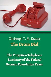
Christoph T. M. Krause lives in Cologne, Germany. He is a passionate collector of old telephones. The Drum Dial has taken him by storm. Krause loves its design, colours, compact workmanship in its interior and most of all, its unusual way of dialling. Almost all telephones of the 1950s are equipped with rotary dials, but Siemens broke new grounds with the Drum Dial. In this second volume, Krause presents the chronology of newly discovered patents, which, since 1931 and with interruptions due to World War II, were developed over two decades, resulting in an innovative total work of art, a "telephone" that is one of a kind.
Das E-Book können Sie in Legimi-Apps oder einer beliebigen App lesen, die das folgende Format unterstützen:
Seitenzahl: 198
Veröffentlichungsjahr: 2021
Ähnliche


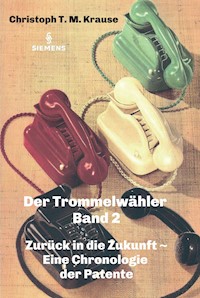


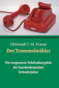


Christoph T. M. Krause - The Drum Dial - Vol. 2
Back the Future -A Chronology of the Patents
Christoph T. M. Krause
The Drum Dial
Vol. 2
Back to the Future -A Chronology of the Patents
© 2021 Christoph T. M. Krause
Cover Design: Christoph T. M. Krause
Author Christoph T. M. Krause, Heerstr. 394a, EU-D-Berlin.
Translation from German: Anja Kadir, EU-D, Elmshorn.
Publisher and Print: tredition GmbH, Halenreie 42, 22359 Hamburg
978-3-347-29269-7 (Paperback)
978-3-347-29270-3 (Hardcover)
978-3-347-29271-0 (e-Book)
This work, including its parts, is protected by copyright.
Any use without consents of publisher and author is prohibited.
In particular, this applies to electronic or other reproduction, translation, distribution and public access.
The publisher has all rights to use pictures and illustrations, presented in this book.
Bibliographic information from the German National Library:
The German National Library lists this publication in the German National
Bibliography; detailed bibliographical data are available via Internet at http://dnb.d-nb.de.
This book is dedicated to my husband
CHRONOLOGICAL OVERVIEW
Year
Kind
Brief Desciption
1932
Forerunner
Drum Dial Apparatus (Built-in table version)
1933
- 1945
World War II
1951
Forerunner
Transverse Handset
1952
Forerunner
Transverse Handset
1952
Supplement/ Enhancement
Finger Stop as Part of the Number Switch
1952
Supplement/ Enhancement
Directory of Participants (discarded)
1953
Supplement/ Enhancement
Separate Jacket for the Number Switch
1953
Conception
The Interior’s Design
1953
Conception
Ground Button
1953
Conception
Handset and Cradle
1953
Conception
The Bell System (upright in order to save internal space)
1955
Conception
Additional Display Device (discarded)
1959
Conception
Modular System of Components
~ II. Patents ~
01. UK Patent Office, 4th February 1932.
a. Patent Specification.
The Forerunner of the Drum Dial Device.
(Built-in Table Version).
As early as 1930, Siemens had opted for an alternative to the dial number switch for switchboards, which was already established in companies and the post office, namely called the "straight pull number switch" (see also “The Drum Dial” Vol. 1, chapter II: “Patenting of the Drum Dial”, p. 14).
Image 05
This pioneer in terms of dial format was patented as early as 1930. At this point in time, I have a copy of the Siemens patent from the patent United Kingdom dated a year later (1931); the German counterpart resp. its predecessor has so far not been found.
Image 06
Since, for our purpose, the British counterpart has the same effect, please find it, in follow-up to Vol. 1, presented below.
The pull number switch is to be installed in a telephone switching desk unit, so that the top is above the desk horizon and the bottom with the corresponding mechanics is below it.
The dialing device is able to accommodate a conventional number switch inside, which in this combination is installed perpendicularly parallel to the pivot axis.
Fig. 2 shows 10 finger recesses in a row, one below the other, with lettering on the plate below showing 10 numbers (1-0) on the left side and 10 letters (A-J) on the right side (in order to be able to serve the areas in their dialing system, which contain letters in addition to digits). The length of this finger unit variant had to be limited due to the narrow installation plan.
Not practical from a later point of view and therefore discarded, the slightly curved inscription or finger control unit can still be seen on the patent drawing, namely in an experimental state (fig. 2). However, the respective future development can already be seen in fig. 3.
Fig 3, accordingly, shows the variant of 2 × 5 staggered finger recesses that are offset from one another, that is to say five on the left-hand side and five on the right-hand side respectively. The necessary filling of the hollows with numbers is not mentioned here.
It can already be seen here that this shorter variant of the finger unit has a decisive advantage, since it requires less space for installation, especially with regard to the subsequent installation plan for the Drum Dial.
Whether this development in favour of the Drum Dial was anticipated at this point in time is not known and it is rather unlikely, as it took another 20 years for it to be developed.
It is thus clear that the development of the later Drum Dial was an innovative product of the post-war period, but its forerunner in terms of number switches (here pull number switches) was developed 20 years earlier, before World War II, and ultimately shaped the design of the Drum Dial and made it possible in the first place.
With this, Siemens proves that it relied on innovative developments with regard to improvements in usability and ergonomics at an early stage.
Patent Specification
RESERVE COPY
PATENT SPECIFICATION
Convention Date (Germany): June 18, 1980..
366.408
Application Date (in United Kingdom): June 18, 1981.
Nr. 17.708/81.
Complete Accepted: Feb 4, 1982
COMPLETE SPECIFICATION.
Improvements relating to Impulse Transmitters Used in Telephone Systems.
WE, SIEMENS & HALSKE AKTIENGESELLSCHAFT, a German Company, of Berlin-Siemensstadt, Germany, do hereby declare the nature of this invention and in what manner the same is to be performed, to be particularly described and ascertained in and by the following statement: -
The present invention relates to an impulse transmitter such as is used in automatic telephone systems for the generation of current impulses.
The impulse transmitter or number dial in common use has a finger plate provided with finger holes the plate being fixed transversely to the dial spindle and is parallel to the base plate of the dial. It is set by inserting a finger in a hole in the finger plate and turning the plate, the finger moving in a circular path about the dial spindle.
It has been found that in certain circumstances operation of the dial leads to soreness or damage of the user’s finger. At an operator’s position where a dial is constantly used this may take place as in some cases 100 settings of the dial per hour may be involved.
The main cause of such trouble is that in the setting of the dial there is a relative turning movement of the finger in the finger hole.
Apart from the foregoing the turning of the finger plate about its centre when the finger is substantially at right angles to the plate is not the easiest movement for the hand of the user and requires more expenditure of effort than a straight line movement, so that in the frequent use of the ordinary finger plate the hand of the user is noticeably tired after a short time.


