177,99 €
Mehr erfahren.
- Herausgeber: John Wiley & Sons
- Kategorie: Fachliteratur
- Serie: Adhesion and Adhesives - Fundamental and Applied Aspects
- Sprache: Englisch
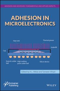
This comprehensive book will provide both fundamental and applied aspects of adhesion pertaining to microelectronics in a single and easily accessible source. Among the topics to be covered include;
- Various theories or mechanisms of adhesion
- Surface (physical or chemical) characterization of materials as it pertains to adhesion
- Surface cleaning as it pertains to adhesion
- Ways to improve adhesion
- Unraveling of interfacial interactions using an array of pertinent techniques
- Characterization of interfaces / interphases
- Polymer-polymer adhesion
- Metal-polymer adhesion (metallized polymers)
- Polymer adhesion to various substrates
- Adhesion of thin films
- Adhesion of underfills
- Adhesion of molding compounds
- Adhesion of different dielectric materials
- Delamination and reliability issues in packaged devices
- Interface mechanics and crack propagation
- Adhesion measurement of thin films and coatings
Sie lesen das E-Book in den Legimi-Apps auf:
Seitenzahl: 526
Veröffentlichungsjahr: 2014
Ähnliche


Contents
Cover
Half Title page
Title page
Copyright page
Preface
Acknowledgements
Part 1: Adhesion: Fundamentals and Measurement
Chapter 1: Study of Molecular Bonding or Adhesion by Inelastic Electron Tunneling Spectroscopy, with Special Reference to Microelectronics
1.1 Introduction
1.2 Principles of IETS
1.3 Application of IETS in Microelectronics
1.4 Prospects
1.5 Summary
References
Chapter 2: Adhesion Measurement of Thin Films and Coatings: Relevance to Microelectronics.
2.1. Introduction
2.2 Mechanical Methods
2.3 Laser Based Techniques
2.4 Summary and Remarks
References
Part 2: Ways to Promote/Enhance Adhesion
Chapter 3: Tailoring of Interface/Interphase to Promote Metal-Polymer Adhesion
3.1 Introduction
3.2 New Concepts for Ideal Design of Metal-Polymer Interfaces with Covalently Bonded Flexible Spacer Molecules
3.3 Situation at Al Oxide/Hydroxide Surfaces Using Aluminium as Substrate
3.4. Adhesion Promotion by Non-specific Functionalization of Polyolefin Surfaces
3.5 Methods for Producing Monosort Functional Groups at Polyolefin Surfaces
3.6 Reactions and Bond Formation at the Interface
3.7 Grafting of Spacer Molecules at Polyolefin Surfaces
3.8 Summary and Conclusions
Acknowledgement
References
Chapter 4: Atmospheric and Vacuum Plasma Treatments of Polymer Surfaces for Enhanced Adhesion in Microelectronics Packaging
4.1 Introduction
4.2 Plasma Fundamentals
4.3 Survey of Vacuum Plasma Treatment of Polymers
4.4 Survey of Atmospheric Pressure Plasma Treatment of Polymers
4.5 Atmospheric Pressure Plasma Activation of Polymer Materials Relevant to Microelectronics
4.6 Vacuum Versus Atmospheric Plasmas for Use in Semiconductor Packaging
References
Chapter 5: Isotropic Conductive Adhesive Interconnect Technology in Electronics Packaging Applications
5.1 Introduction
5.2 ICA Technology
5.3 Technology Reviews
5.4 Electrical Properties
5.5 Mechanical Properties
5.6 Thermal Properties
5.7 Metallic Filler
5.8 Polymer Materials
5.9 Reliability
5.10 Dispensation
5.11 Environmental Properties
5.12 Other Results
5.13 Summary
5.14 Prospects
References
Part 3: Reliability and Failure Mechanisms
Chapter 6: Role of Adhesion Phenomenon in the Reliability of Electronic Packaging
6.1 Introduction
6.2 Hierarchy of Electronic Packaging
6.3 Substrates, Carriers, and Laminates
6.4 Flexible Laminates
6.5 First Level Packaging /Semiconductor Packaging
6.6 Second Level Packaging
6.7 Reliability Enhancements
6.8 Thermal Management
6.9 Summary
Acknowledgements
References
Chapter 7: Delamination and Reliability Issues in Packaged Devices
7.1 Introduction
7.2 Basic Aspects of Delamination Failure
7.3 Evaluation of Delamination Initiation in Electronic Packages
7.4 Evaluation of Delamination Propagation in Electronic Packages
7.5 Summary
References
Chapter 8: Investigation of the Mechanisms of Adhesion and Failure in Microelectronic Packages
8.1 Introduction
8.2 Thermal Methods of Characterization
8.3 Stresses in Encapsulated Devices
8.4 More on Adhesion of Molding Compounds
8.5 Summary
References
Adhesion in Microelectronics
Scrivener Publishing 100 Cummings Center, Suite 541J Beverly, MA 01915-6106
Adhesion and Adhesives: Fundamental and Applied Aspects The topics to be covered include, but not limited to, basic and theoretical aspects of adhesion; modeling of adhesion phenomena; mechanisms of adhesion; surface and interfacial analysis and characterization; unraveling of events at interfaces; characterization of interphases; adhesion of thin films and coatings; adhesion aspects in reinforced composites; formation, characterization and durability of adhesive joints; surface preparation methods; polymer surface modification; biological adhesion; particle adhesion; adhesion of metallized plastics; adhesion of diamond-like films; adhesion promoters; contact angle, wettability and adhesion; superhydrophobicity and superhydrophilicity. With regards to adhesives, the Series will include, but not limited to, green adhesives; novel and high-performance adhesives; and medical adhesive applications.
Series Editor: Dr. K.L. Mittal 1983 Route 52, P.O. Box 1280, Hopewell Junction, NY 12533, USA Email: [email protected]
Publishers at Scrivener Martin Scrivener([email protected]) Phillip Carmical ([email protected])
Copyright © 2014 by Scrivener Publishing LLC. All rights reserved.
Co-published by John Wiley & Sons, Inc. Hoboken, New Jersey, and Scrivener Publishing LLC, Salem, Massachusetts. Published simultaneously in Canada.
No part of this publication may be reproduced, stored in a retrieval system, or transmitted in any form or by any means, electronic, mechanical, photocopying, recording, scanning, or otherwise, except as permitted under Section 107 or 108 of the 1976 United States Copyright Act, without either the prior written permission of the Publisher, or authorization through payment of the appropriate per-copy fee to the Copyright Clearance Center, Inc., 222 Rosewood Drive, Danvers, MA 01923, (978) 750-8400, fax (978) 750-4470, or on the web at www.copyright.com. Requests to the Publisher for permission should be addressed to the Permissions Department, John Wiley & Sons, Inc., 111 River Street, Hoboken, NJ 07030, (201) 748-6011, fax (201) 748-6008, or online at http://www.wiley.com/go/permission.
Limit of Liability/Disclaimer of Warranty: While the publisher and author have used their best efforts in preparing this book, they make no representations or warranties with respect to the accuracy or completeness of the contents of this book and specifically disclaim any implied warranties of merchantability or fitness for a particular purpose. No warranty may be created or extended by sales representatives or written sales materials. The advice and strategies contained herein may not be suitable for your situation. You should consult with a professional where appropriate. Neither the publisher nor author shall be liable for any loss of profit or any other commercial damages, including but not limited to special, incidental, consequential, or other damages.
For general information on our other products and services or for technical support, please contact our Customer Care Department within the United States at (800) 762-2974, outside the United States at (317) 572-3993 or fax (317) 572-4002.
Wiley also publishes its books in a variety of electronic formats. Some content that appears in print may not be available in electronic formats. For more information about Wiley products, visit our web site at www.wiley.com.
For more information about Scrivener products please visit www.scrivenerpublishing.com.
Library of Congress Cataloging-in-Publication Data:
ISBN 978-1-118-83133-5
Preface
The phenomenon of adhesion is of cardinal importance in variegated ways in the domain of microelectronics. A few eclectic examples will suffice to underscore the importance of adhesion in this industry. Adequate adhesion of thin films is sine qua non in integrated circuits; requisite adhesion of polymer and other materials is a must in packaged devices; adhesion of various materials is crucial in fabricating printed circuit boards. Many failures in the microelectronics industry can be traced to lack of proper adhesion or are imputed to sub-optimum interfaces between different materials used. This necessitates study and characterization of interfaces/interphases, devising ways to modify surfaces of materials to attain the desired level of adhesion between the mating partners; use of bonding agents and adhesion promoters. Also, the need for reliable methods of adhesion measurement is quite patent. Moreover, the reliability aspects of components and devices in the microelectronics industry is of grave concern.
Although there has been a high tempo of R&D activity, the information is scattered in a number of publication media. There is no single easily accessible source where one can find the requisite information on adhesion in microelectronics. This lacuna in the literature provided vindication for this book, which we felt was both timely and needed.
This book containing 8 chapters by subject matter experts is divided into three parts: Part 1: Adhesion: Fundamentals and Measurement; Part 2: Ways to Promote/Enhance Adhesion; and Part 3: Reliability and Failure Mechanisms. The topics covered include: application of inelastic electron tunneling spectroscopy (IETS) in understanding fundamental nature of bonding (adhesion); a number of techniques (qualitative, semi-quantitative, quantitative) for adhesion measurement of thin films and coatings; tailoring of interfaces/ interphases to promote adhesion of metal layers on polymers; application of plasma (both vacuum and atmospheric) treatments of polymer surfaces for enhanced adhesion to other materials; isotropic conductive adhesives in electronic packaging applications; role of adhesion phenomena in the reliability of electronic packaging; delamination and reliability issues in packaged devices; and mechanisms of adhesion and failure in microelectronic packages, especially at the molding compound/substrate interface.
Individuals in academia carrying out research in understanding and unraveling the fundamental aspects of adhesion of similar or dissimilar materials and those involved/interested in various aspects of adhesion in microelectronics should find this book of extreme interest. The information contained in this book should be of immense appeal to R&D, manufacturing and quality control personnel. In essence, anyone interested (peripherally or centrally) in improving adhesion in various microelectronic components and devices should find this treatise of great value. It should serve as a gateway for neophytes and a commentary on recent developments for the seasoned researcher.
This book should also be of interest to those working in other industries where understanding and control of adhesion is of paramount importance, such as thin film technology, optics, packaging of all sorts of products, adhesive bonding, aerospace, metallized plastics, encapsulation.
Acknowledgements
Now comes the pleasant task of thanking those who were instrumental in giving this book a body form. First of all, we are beholden to the authors for their interest, enthusiasm, cooperation and contributing their chapters, without which this book would not have seen the light of day. Also we very much appreciate the steadfast interest and unwavering support of Martin Scrivener (publisher) in this book project.
Kash Mittal P.O.Box 1280 Hopewell Jct., NY 12533 E-mail: [email protected]
Tanweer Ahsan Henkel Electronic Materials LLC 1400 Jamboree Road Irvine, CA 92606 E-mail: [email protected]
April 14, 2014
Part 1
ADHESION: FUNDAMENTALS AND MEASUREMENT
Chapter 1
Study of Molecular Bonding or Adhesion by Inelastic Electron Tunneling Spectroscopy, with Special Reference to Microelectronics
Robert R. Mallik
Department of Physics, The University of Akron, Akron, Ohio USA
E-mail: [email protected]
Abstract
This chapter presents an outline of the principles, methods, applications, and scope of Inelastic Electron Tunneling Spectroscopy (IETS) with emphasis placed on the study of molecular adsorption on metal oxide and semiconductor surfaces. Strengths and limitations of the technique are highlighted, with particular attention being paid to applications in adhesive systems comprised of materials pertinent to microelectronics device fabrication including epoxy resins, polyimides, and silanes. A brief description of how IETS may be used to investigate adsorption and conduction mechanisms for self-assembled monolayers of molecules adsorbed on photovoltaic semiconductor materials is given as a segue into an examination of how IETS and related techniques are being developed for the study of molecules of interest in the rapidly developing field of molecular electronics.
Keywords: Adhesion, microelectronics, molecular electronics, photovoltaics, thin-films, vibrational spectroscopy, IETS.
1.1 Introduction
The potential of IETS in various, and seemingly diverse, research areas such as surface chemistry, heterogeneous catalysis, analytical chemistry, environmental pollution monitoring, adhesion science, radiation damage, biological chemistry and electronic energy level studies was recognized early in the development of the technique [10]. Of particular interest for the present chapter, as will be shown, is early work illustrating the usefulness of IETS in the study of numerous adhesive systems, for example silane coupling agents on alumina [11, 12, 13, 14, 15, 16, 17], and other adhesive, or adhesive-related, systems on alumina including epoxides [18, 19, 20], polymers [21, 22], and phenolics [23]. Since aluminum is the base electrode of choice for most IETS work, and because aluminum is a widely used material for adhesive bonding in aerospace, automotive, and packaging applications, it is perhaps not surprising that IETS was deemed particularly appealing for such adhesion studies. Since these early studies, it should be noted that IETS has also been applied to other adhesive systems for example systems of adhesion promoters on glassy substrates [24]. More recently, IETS has been used to study adsorption on materials other than the native oxide of the base electrode metal, i.e., on so-called artificial tunnel barriers. In 1989, Barner and Ruggiero reported the material and electron tunneling properties of thin radio-frequency magnetron sputtered alumina films supported on copper base electrodes [25]. Around the same time, Mazur and Cleary demonstrated the potential utility of an aluminum nitride artificial barrier deposited by reactive ion-beam sputtering [26], and two years later, it was reported that sputtered amorphous silica formed a viable artificial tunnel barrier when deposited onto gold base electrodes [27]. These and subsequent studies on artificial tunnel barriers were significant in that they demonstrated that the technique of IETS could be extended to investigate a wider range of systems than just those involving adsorption studies on alumina. IETS has now been successfully performed on other semiconductor barriers [28, 29], including photovoltaics [30], and it has also been used to the study molecular adsorption on photovoltaics [31] illustrating how the technique may be applied to materials of interest in the area of microelectronics.
1.2 Principles of IETS
1.2.1 General Overview
As outlined in the Introduction, IETS relies on the quantum mechanical phenomenon of electron tunneling between two metal electrodes through a sufficiently thin potential barrier. It allows one to measure the vibrational energies of molecular species constituting the barrier when excited by these tunneling electrons. Barriers are incorporated in metal/insulator/metal tunnel junctions fabricated sequentially on insulating substrates by conventional vacuum deposition techniques. They must be uniformly thin (of the order of 2–3 nm) and continuous if sufficient tunnel current is to flow. Monolayers of compounds of interest may be introduced onto the barriers if desired. Resulting IET spectra yield information regarding the nature of molecular bonding at the interface so formed. IR, Raman, and other modes in the barrier and metal electrodes are detectable, and IET peak intensities may be correlated to surface coverage, bond angles, and the location of bonds within the tunnel barrier [2, 32].
A description of how IETS is applied in practice, describing the above items in more detail, is given in sections 1.2.2, 1.2.3 and 1.2.4 below.
1.2.2 Key Principles of Operation
Tunneling is induced by the application of a small dc bias voltage, V, between the two metals which offsets their Fermi energies, EF1 and EF2, by an amount, eV, as indicated in Figure 1.1(a).
Figure 1.1 (a) Schematic diagram of a metal/insulator/metal IET junction. Hatched regions indicate filled electron energy states. The insulating barrier, I, may be the native oxide of the base electrode (metal 1), or an artificial barrier deposited onto metal 1 as described in section 2.4.2 of the text. Molecular species may be introduced onto the barrier if desired to create a composite tunnel barrier. (b) The effect of the bias voltage is to offset the Fermi energies of metal 1 and metal 2, EF1 and EF2 respectively, by an amount eV, causing electrons to tunnel from filled energy states in metal 1 through the insulating barrier to empty states in metal 2. Almost all electrons (approximately 99%) tunnel elastically, but a small fraction does so inelastically by interacting with vibrational modes in the barrier.
Electrons tunnel from filled states close to the Fermi energy of one metal to empty ones in the other, and most do so by traversing the barrier elastically i.e., with no loss of energy; but a small fraction (<1%) does so inelastically by transferring energy to species within the barrier (see Figure 1.1(b)). The I-V relationship of an IET junction solely due to elastic tunneling is nominally linear over the voltage range of interest (0 to 500 mV), however, the onset of inelastic events produces small increases in current at specific threshold voltages corresponding to the energies of vibrational modes of barrier species, the net effect on the I-V curve being corresponding increases in slope at these threshold voltages as shown in Figure 1.2(a).
Some important factors which affect IETS peak intensities must be considered when interpreting IET spectra. Firstly, as is the case for all vibrational spectroscopies, peak intensities correlate with the number of (dipole) bonds excited. Secondly, IETS peak intensities also depend on the orientation of the bonds with respect to the plane of the tunnel junction. In general, IETS peaks are stronger for bonds whose axes are aligned perpendicular to the plane of the junction and weaker for bonds whose axes lie parallel to it. This is because electrons tunneling from one metal electrode to the other through the barrier couple most strongly with bonds that are coaxial with their tunneling path. Thirdly, IETS peak intensities correlate with a bond’s location within the tunnel barrier. This is a consequence of the localized nature of the electron-mode interaction in the tunneling process and manifests itself as a bias polarity dependent peak intensity asymmetry. Forward bias in IETS is defined as the case where the cover electrode is positive with respect to the base electrode, therefore electrons tunnel from the base electrode to the cover electrode, while reverse bias is defined in the opposite sense. If one assumes that a particular mode is, for example, situated at the cover electrode side of the junction it is more probable that an electron will tunnel elastically with higher energy from the base electrode through the barrier towards cover electrode and then inelastically excite the mode (i.e., under the forward bias condition) rather than first interacting inelastically with the mode and then tunneling elastically through the remainder of the barrier towards the base electrode with a lower energy (reverse bias). Therefore, the peak associated with the mode located at the cover electrode side of the junction would appear stronger under forward bias and weaker under reverse bias. A schematic depiction of the two processes is given in Figure 1.3.
Figure 1.3 (a) Energy diagram for an IET junction with zero applied bias. A rectangular barrier of height, φ, is a reasonable approximation to a real barrier. Located towards the metal 2 side of the barrier is a moiety with vibrational mode energy, hv, indicated by a filled circle. (b) Under the forward bias condition, electrons first tunnel elastically through the barrier, then excite the moiety through an inelastic interaction. After losing energy to the moiety, the electrons emerge on the other side of the barrier and occupy the lowest available empty energy states. (c) Under reverse bias, electrons interact inelastically first with the moiety before tunneling through the remainder of the barrier with a lower energy. Since tunneling probability decreases with electron energy, the process shown in this figure is, on average, less likely than that of Figure 1.3(b). The effect of this phenomenon is that the IETS peak associated with the moiety under reverse bias is weaker than for the forward bias case.
This phenomenon has been invoked to isolate the position of Si-H moieties in sputtered amorphous SiO films. It was demonstrated that the Si-H moieties were created on the SiO surface during the fabrication process and could be subsequently removed by exposure to a plasma discharge in vacuo [33].
1.2.3 IET Spectrometer Design and Implementation
At present, no commercial IET spectrometers are available so in-house built instruments are used in research laboratories, several of which are described in the literature [3]. They employ a widely used spectroscopic method for small signal recovery namely modulation of the input signal at a fixed frequency, ω, coupled with phase-sensitive detection of output signal harmonics generated due to non-linear sample responses [34]. Figure 1.4 shows the typical IET spectrometer design. The spectrometer applies a small modulation current, Iω, superimposed upon a slowly ramped dc bias voltage, V, across the IET junction. Taylor series analysis shows that the second harmonic voltage response, V2ω, developed across the junction is proportional to the quantity d2I/dV2. (The magnitude of V2ω depends on that of the slope changes of the junction’s I-V curve and Iω). V2ω is recovered experimentally by a lock-in amplifier.
Figure 1.4 Schematic diagram of a constant resolution IET spectrometer. A digital-to-analog converter (DAC) supplies a ramped dc bias voltage, V, while an oscillator provides a small ac modulation current Iω. A mixer circuit isolates the dc and ac power sources, combines the dc bias voltage and ac modulation current, and applies them simultaneously to the junction. In response to the applied modulation current, an ac modulation voltage, Vω, and corresponding second harmonic, V2ω, develops across the junction. A lock-in amplifier (LIA) is used to recover the second harmonic voltage, while the dc bias voltage is measured by a digital multi-meter (DMM). In order to maintain constant resolution across the entire dc bias range, a regulator circuit monitors Vω across the junction in a feedback loop and adjusts the oscillator current output as necessary such that Vω remains essentially constant. Commercial software packages are normally used to control the various instruments in the spectrometer via a GPIB interface and plot the resulting IET spectra (i.e, V2ω versus bias voltage).
1.2.4 IET Sample Preparation
Many reviews of IETS are available [2, 3, 8, 10] which describe fully the metal/tunnel barrier/metal sample fabrication process so only brief description is given here paying particular attention to samples with semiconducting barriers of potential importance in the area of microelectronics and photovoltaics. Sample preparation consists of sequential deposition of the metal base electrode, tunnel barrier, and cover electrode.
1.2.4.1 Electrode Deposition
Base and cover electrodes are nearly always deposited by thermal evaporation onto glass microscope slides through shadow masks to define the electrode geometry. Resistively heated evaporation sources are employed and the procedure is performed in a conventional high vacuum chamber at pressures of the order of 10−5 to 10−7 Torr. The IETS base and cover electrodes are usually aluminium and lead, respectively.
1.2.4.2 Barrier Preparation
Tunnel barriers may be formed in a variety of ways. Native oxides of the base electrode metal are by far the most common barriers and are formed either by exposing the electrodes to a low-pressure oxygen plasma (of order 100 mTorr) while in the vacuum chamber to form a plasma oxide or simply by venting the chamber to atmosphere to form a thermal oxide. In both cases, the oxides created are typically 2–3 nm thick. Artificial barriers (insulators or semiconductors) may also be deposited directly onto the (un-oxidized) base metal electrodes by radio-frequency magnetron sputtering in an inert (e.g. argon) or reactive (e.g., oxygen) plasma. Such artificial barriers must be formed under low-power conditions to ensure a sufficiently low deposition rate which is vital to ensure that the barriers are sufficiently thin and continuous. Typical powers and deposition rates are approximately 5 W, and 0.01 nm/s respectively [27]. Figure 1.5 shows an AFM image of a CdTe film deposited in this way.
Figure 1.5 AFM image of an ultra-thin film CdTe artificial tunnel barrier prepared by radio-frequency magnetron sputtering. X and y length scales are the same. To simulate experimental conditions in IETS, the film was grown on an underlying aluminum thin film (approximately 300 nm thick) vacuum evaporated previously onto a clean glass microscope slide consistent with standard practice for IETS base electrodes as described in section 1.2.4. The CdTe film was deposited in a 50 mTorr background of Ar, by employing a very low power and deposition rate (~5W rms, and ~0.02 nm/s respectively). These conditions are required such that extremely small clusters of the CdTe target material are ejected during the sputtering process to grow a film which is sufficiently uniform and thin enough for IETS purposes. Films of this type display a granular structure; this particular film has an rms roughness of 0.82 nm, and is 16.5 nm thick.
If desired, molecular species may be deposited onto the barriers. This is normally achieved by spin coating the barrier with a very dilute solution of the compound in question (typical concentrations are of the order 0.1% w/v) or by exposing the barrier to a vapour of the compound preferably in a fume hood. The former method is normally referred to as liquid phase doping and the latter vapor phase doping. For both, the solution concentration and exposure times are varied by trial-and-error with the goal of achieving near-monolayer coverage of adsorbate.
1.3 Application of IETS in Microelectronics
Adhesive bonding plays a major role in the manufacture of microelectronic devices, assemblies, and packaging as described in a thorough review article by Yacobi and co-workers [37]. During the device fabrication process, it is often necessary to bond dissimilar materials such as metals, semiconductors, and polymers. The goal, when bonding such materials, is to minimize any possible adverse effects that may arise due to the bonding process, for example the creation of stresses which may lead to a reduction in the structural integrity of the bonded layers which may cause unwanted changes in the electrical properties of the microelectronic devices. Judicious choice of the adhesive system to be employed for the particular materials in the microelectronic device in question is essential for achieving this goal. A pivotal factor in choosing an adhesive system is a detailed knowledge of the physical and chemical adhesion mechanisms at the molecular level which can be provided by surface-sensitive spectroscopic methods.
As mentioned in Section 1.1 above, IETS offers unique capabilities and features which can complement Reflection Absorption IR Spectroscopy (RAIRS) and Raman data. This has practical importance in the study of adhesion at the molecular level. Most often, IETS data are compared with IR, but care must be taken when interpreting the differences. Sondag and coworkers studied monolayers of several aromatic and non-aromatic carboxylic acids chemisorbed on alumina and found that intrinsic differences in sensitivity exist between IETS and conventional RAIRS [38]. They observed that CH vibrations are stronger in IETS while vibrations involving carbon and oxygen atoms, and particularly carbonyl modes, are stronger in RAIRS. The reasons for the differences were not clear but they pointed out that the selection rules were well-established for IR but not so for IETS. In order to elucidate these observations, Devdas and Mallik performed a series of investigations to study specifically chosen carboxylic acids chemisorbed on alumina using IETS and RAIRS in tandem. To ensure similar molecular environments, they used similarly prepared samples with very thin lead cover films for both spectroscopies (normally, RAIRS samples do not have a lead cover film). They found that the cover film, which was sufficiently thin such that it transmitted IR radiation, had a significant effect on carbonyl mode intensities. In fact, they observed that the proximity of the cover film [39], location of particular bonds within molecules [40] and fractional surface coverage of the molecules [41] all have an effect on peak intensities in both IETS and RAIRS. To illustrate this phenomenon, Figure 1.6 shows a comparison of the IET and RAIR spectra for 5-oxoazelaic acid adsorbed on alumina with a surface coverage close to one monolayer.
Figure 1.6 (a) RAIR spectrum of 5-oxoazelaic acid (molecular structure as inset) spin-coated from a dilute solution in ethanol onto aluminum oxide. Carboxylic acids are known to chemisorb on alumina via acid-base reactions of the carboxylic acid group with the amphoteric surface. For the solution concentration used here, the surface coverage of 5-oxoazelaic acid is nominally one monolayer and the molecules are closely packed and adsorbed on the surface via one of the carboxylic acid groups. The strong peak at 1736 cm−1 is due to unreacted carboxylic acid carbonyls and the shoulder at 1703 cm−1 is assigned to the 5-oxo-substituted carbonyls. (b) RAIR spectrum recorded for a sample prepared identically to the one of Figure 6(a) except that it was capped by a very thin (~20 nm) lead film evaporated on top of the 5-oxoazelaic acid monolayer in order to simulate conditions used in IETS. The effect of the lead film is to suppress the unreacted carboxylic acid carbonyl peak, while the 5-oxo-substituted carbonyl peak is essentially unaffected and appears at 1705 cm−1. (c) IET spectrum recorded for a sample prepared identically to that of Figure 6(b) except a thicker lead film was deposited (~100nm). The 5-oxo-substituted carbonyl peak appears at 1704 cm−1. Note that hydrocarbon stretching modes (ca ~2900 cm−1) are much stronger in the IET spectrum than in RAIR spectrum as is generally the case for most compounds.
As can be seen, if a lead cover film is deposited onto the adsorbed monolayer to cap the structure, vibrations of the unreacted carboxylic acid carbonyl group in the molecule are suppressed in both IET and RAIR spectra. The findings taken as a whole illustrate the benefit of using both IETS and RAIRS in conjunction when investigating adsorbed monolayers which should be taken into consideration when interpreting data for systems of adhesives and in general.
IETS has been used to study several adhesive-related systems including phenolic adhesives [23], phosphorous acids [42] and silane coupling agents [11–17] all of which are important for improving adhesion for components in printed circuit board manufacture, specifically those related to encapsulation and packaging purposes.
It is well known that insulating polymer films are of significant technological importance in the fabrication of microelectronic devices. IETS has enjoyed success for some years in the investigation of adhesives [19, 43] and may be applied to adhesive systems of interest in microelectronics. The primary reason for this is that IETS is well suited to systems consisting of thin insulating layers (often polymeric in nature) adsorbed on metal oxides. For example, one family of compounds, epoxy resins, which is widely used in microelectronics for bonding, packaging, and dielectrics layers in printed circuit board assemblies has been studied by IETS. Figure 1.7 shows the IET spectrum of a model compound synthesized to simulate an amine cured epoxy resin obtained by Affrossman and coworkers [44]. The compound (the adduct of reaction of the diglycidylether of bisphenol A with excess diethylamine) was used in order to avoid difficulties associated with preparing ultra-thin resin layers necessary for IETS, or extrapolating information from the study of separate components of cured resins as the compound itself already has a structure similar to a fragment of cured resin. The compound was introduced onto alumina by spin-coating from a dilute solution in benzene followed by repeated degassing under vacuum to remove excess unreacted amine.
Figure 1.7 IET spectrum of the adduct of reaction of the diglycidylether of bisphenol A with excess diethylamine adsorbed on alumina. The adduct was synthesized as a model compound to study the adsorption of epoxy resins on alumina since its structure is similar to a fragment of cured epoxy resin.
Figure reproduced from reference [44] by permission of Elsevier.
Based on their detailed spectral analysis, these researchers suggested that the compound is chemisorbed on alumina by the loss of a proton from the adsorbate to give a surface bound alkoxy or alkoxide species. Concomitant with their proposed deprotonation scheme – i.e., alkoxy/alkoxide chemisorption – they further postulated that the structure of the adsorbate would allow the formation of a chelated surface complex with tetrahedral, or octahedral, coordination at surface aluminum cations.
A further early illustration of the effectiveness of IETS in studying epoxies is an investigation whereby the IET spectrum of an adduct of n-propylamine and 1,2,-epoxy butane adsorbed on alumina (at 4.2 K) was compared with low temperature matrix isolation IR data (at 12 K) for the “free” molecule. The study showed that the adduct, which contains the –N(H)-C-C(OH) group, reacts strongly with the alumina surface via a reaction in which the nitrogen abstracts a proton from the surface that is consistent with the adsorbed species being bound to the surface in a chelate-type structure [45]. This work highlights once more that the use of IETS coupled with IR measurements, and in particular multiple specular reflection surface IR techniques, is very useful in general for investigating surface reactions at the monolayer adsorbate level.
Another family of compounds that has found increased use in microelectronic device applications is polyimides. These compounds are used as fabrication aids, passivants and interlevel insulators, adhesives, and components of matrix resins for fiber-reinforced composites of substrates and circuit boards [46]. The most commonly used polyimides for commercial microelectronics use are condensation polyimides, often formed from imidization of a spin-cast film of soluble poly(amic acid) precursor to create an intractable solid film, but fully imidized thermoplastic polyimides (when thermally-, or photo-cross-linked) are also sometimes used. In many microelectronic applications, an understanding of the adhesion mechanisms between metal layers and (i) insulating substrates and/or (ii) semiconductor layers is of vital practical importance. Such an understanding is key in improving the structural integrity and durability of the associated microelectronic devices. IETS has been used to study phthalimides adsorbed on alumina as a model for polyimide adhesion and detailed information on the configuration and adsorption mechanisms was obtained by Ramsier and Henriksen [47]. Spectroscopic evidence was discovered for a strong interaction between the substituted benzene rings and the alumina surface, and Al-N complexing between the rings and the surface. The observations are consistent with the phthalimides being adsorbed with the rings in a flat configuration with respect to the surface. Figure 1.8 shows an IET spectrum of phthalimide spin-coated onto alumina from a dilute solution in ethanol [47].
Figure 1.8 IET spectrum of phthalimide adsorbed on alumina. The strong peak at 2855 cm−1 is believed to be an N-H stretching mode originating from reactions between the phthalimide molecules and the surface. The mode is perturbed (down-shifted in energy) from its unbound state due to hydrogen bonding between adjacent phthalimide molecules adsorbed on the alumina surface. A flat adsorbed configuration for the phthalimide molecules is consistent with the spectral data which displays a peak at 411 cm−1 due to Al-N vibrations indicative of Al-N complexing between the phthalimide rings and the alumina surface. Polyimides containing the same monomer units would be expected to exhibit similar adsorption mechanisms.
Figure reproduced from reference [47] by permission of the Society for Applied Spectroscopy.
Various (relatively weak) phthalimide ring modes are observed in the 500 to 1600 cm−1 region of the spectrum, but of particular interest to these researchers was the strong band at 2855 cm−1 which, they surmised, arose mainly from fundamental interactions between the phthalimide molecules. They attributed the 2855 cm−1 band to a N-H stretching mode that was perturbed (down-shifted in energy) from its unbound state due to hydrogen bonding between adjacent phthalimide molecules adsorbed on the alumina surface. This is supported, in part, by the fact that the free N-H stretching mode (ca 3200 cm−1 for phthalimides) is absent in the spectrum. Further, they noted that since the ring modes of the phthalimide molecules are relatively weak, a flat adsorbed configuration of the molecules is most probable (because IETS peaks are weaker when molecular bond axes are perpendicular to the direction of electron tunneling as in the case for this flat adsorbed configuration). Such a flat configuration is conducive to Al-N complexing between the phthalimide rings and the alumina surface and they assigned the peak at 411 cm−1 to Al-N vibrations. From these results it was inferred that polyimides containing the same monomer units would be expected to exhibit similar adsorption mechanisms.
Perhaps the most widely studied compounds in IETS, with respect to adhesives and adhesion promoters, are organofunctional silanes which are well-known to many researchers in the field of adhesion. This family of compounds is described fully in the seminal book by Plueddemann [48] and in a comprehensive series of volumes by Mittal [49, 50, 51, 52, 53]. Mittal and coworkers also used IETS to investigate the effect of high relative humidity and exposure time on the silane/alumina interface [13, 14] which is of significant practical importance in the field of adhesion since adhesive joints are often exposed to water, in liquid or vapor form, in actual working environments. Figure 1.9 shows the IET spectrum of aminophenyltrimethoxysilane on alumina [13].
Figure 1.9 IET spectra of aminophenyltrimethoxysilane adsorbed on alumina. (a) As deposited. (b) After exposing to 100% relative humidity for 4 h. (c) After exposing to 75% relative humidity for 18 h. (d) The differential spectrum (a) – (c).
Figure reproduced from reference [13] by permission of John Wiley and Sons.
The silane was introduced onto the alumina by exposure to the silane vapor created by heating the silane liquid in a separate vacuum chamber under controlled conditions. Figure 1.9 also shows spectra obtained after exposing the completed silane-doped IET junction to different humidity conditions. It is known that water vapor can penetrate IET junctions, via the somewhat porous lead cover electrode, by a process known as infusion doping [54, 55, 56], and this phenomenon was exploited in order to allow water to access the silane/alumina interface. In this way the (pristine) silane-doped IET junction was exposed to an environment of saturated water vapor (100% relative humidity) at 23°C for 4h. The junction was then dried out in a vacuum chamber at a pressure of 0.1 Torr for 20 minutes to remove excess water, and its spectrum was recorded. After this the junction was further exposed to a 75% relative humidity atmosphere for 18 h, dried as before and its spectrum recorded again. As can be seen, with increasing exposure to high relative humidity environments the intensities of the CH3 stretching modes (ca 2800–3000 cm−1) and CH3 deformation modes (1450 cm−1) are reduced significantly and this is attributed to the hydrolysis of the methoxy group and subsequent removal of the resultant methanol by-product from the tunnel barrier. The same researchers conducted similar studies on another widely used silane, namely γ-aminoproplytriethoxysilane [14]. Adopting essentially the same technique described above for aminophenlytrimethoxysilane, the γ-aminoproplytriethoxysilane was introduced onto the alumina surface in vapor form, then the completed IET junction was exposed to a 75% relative humidity environment for increasing exposure times. Figure 1.10 shows the spectra obtained from the IET junction after these exposures.
By carefully and systematically monitoring changing intensities of specific spectroscopic bands (most notably CH3 stretching and deformation, amine, and OH stretching) over increasing exposure time to high humidity, these researchers were able to propose a detailed scheme whereby the silane molecules first reorient on the surface after the initial 6 h exposure period, then the majority of initially adsorbed silane molecules desorb with increasing exposure to high humidity, and after this the remaining silane undergoes hydrolysis. They postulated that the hydrolysis by-product (ethanol) is likely oxidized to acetaldehyde on the alumina surface and the initially unhydrolyzed silane is probably hydrogen bonded via its NH2 groups to surface OH groups on the alumina. The two studies above on the effect of humidity on the silane/alumina interface give a good indication of the remarkable level of detail and sensitivity that can be achieved by IETS in monitoring surface-specific reactions.
Silane coupling agents have particular significance in the context of microelectronics since the majority of microelectronic devices are still fabricated on silicon wafers. Silanes are also widely used in the fabrication of printed circuit boards (PCBs) as laminates to enhance adhesion between imbedded glass fiber reinforcements and the matrix (typically an epoxy resin) of the PCBs [57]. An understanding of the adsorption of silanes on glassy substrates therefore is of vital practical importance in microelectronics. As mentioned in the Introduction, most adsorption studies in IETS have been conducted for compounds on alumina, silanes being no exception, and many studies have been published over the years [11–17]. However, IETS has also been shown to be viable for the study of silanes adsorbed on glass-like materials. For example, work to model silane-glass adhesion by the investigation of adsorbed monolayers of triethoxysilane on germania artificial tunnel barriers has been performed (germania was chosen as the barrier material so that vibrational modes associated with the adsorbent and adsorbate could be distinguished) [58]. This work directly probed adsorption at the monolayer level to verify that the presence of water vapor and surface hydroxyl moieties is key in facilitating surface condensation and hydrolysis reactions between the silane and germania.
Another area closely linked to the microelectronics industry is photovoltaic device manufacture. Crystalline silicon based technology still dominates the industry and, as just described, IETS can be used to investigate adsorption on silicon and its oxides at the monolayer level. However, other materials are increasingly being used and, in particular, thin-film amorphous photovoltaic materials have received considerable attention over the last 15–20 years or so [59]. Devices based on amorphous thin-film photovoltaic materials may be fabricated into lighter, thinner, and more flexible packages but, at present, device efficiency cannot compete with crystalline silicon wafer based technology. One of the main problems is identifying and minimizing defects which can act as trap sites for charge carriers [60]. Adhesion between interlayers in multilayered (amorphous) photovoltaic heterojunctions is of significant practical importance, and IETS offers another way of probing these interfaces. It can be used to study both the adsorption of compounds on the materials from which various layers are fabricated and the associated conduction mechanisms through these layers. To illustrate this, another widely used photovoltaic material, CdS, a direct bandgap semiconductor, has been investigated by IETS. Specifically, it has been used to study the adsorption of a trithia-adamantane anchor based compound (7-ethynyl-2,4,9-trithia-tricyclo[3.3.1.13,7]decane, or 7ETTD) on ultra-thin amorphous CdS films [31]. Junctions of the type Al/CdS/Pb were prepared with and without an adsorbed 7ETTD layer and then, comparing with RAIRS data, it was shown that the 7ETTD molecules self-assemble to form a monolayer adsorbed via their adamantane anchors in a packed configuration. The junctions were considerably non-linear, so NTI methods were needed to maintain constant resolution in the IET spectra [61]. Perhaps more interesting than their spectra are I-V data recorded for the IET junctions which indicated that the junctions’ conductance is increased as a result of the introduction of the adsorbed 7ETTD monolayer.
Figure 1.11 shows conductance versus voltage (G-V) plots for Al/CdS/Pb IET junctions with and without an adsorbed 7ETTD monolayer recorded over a broad range of temperatures (room temperature down to liquid helium, 4.2 K). As can be seen, in addition to increasing the conductance of the junction, the curves become more symmetrical under both forward and reverse bias with the introduction of the 7ETTD monolayer. The data are more complex than first inspection might suggest since different conduction mechanisms come into play at different temperatures. A model has been proposed whereby coupling of HOMO and LUMO levels of the 7ETTD molecules with surface energy states in the CdS energy gap creates conductive pathways through the junctions. These findings show how IETS can be used to probe the electronic properties of very thin semiconductor films. They also suggest that the adamantane compounds may offer some promise in improving performance of photovoltaic devices and hint at the possibility that they may find application in the area of nanotechnology as candidates for molecular wires. Moreover, since the compounds can be functionalized with other groups attached to the adamantane anchor, they may have wider use in molecular electronics, a rapidly developing area focused on miniaturization of electronic devices as will be described in the following section.
Figure 1.11 (a) Conductance (in Siemens) versus bias voltage (V) curves for an Al/CdS/Pb IET junction recorded for temperatures in the range 4.2 K to approximately 300 K. (b) When a 7-ethynyl-2,4,9-trithia-tricyclo [3.3.1.13,7] (or 7ETTD) self-assembled monolayer is introduced onto the CdS surface, to create an Al/CdS/7ETTD/Pb junction, the conductance is significantly increased. It is believed that HOMO and LUMO levels of the 7ETTD molecules couple with CdS surface energy states to provide additional conductive pathways through the junctions. This figure illustrates the potential of compounds of this type in molecular electronics
1.4 Prospects
In recent years, there has been a shift in emphasis of applications of IETS and it is increasingly becoming useful for probing a broader range of systems than just compounds adsorbed on a limited range of metal oxides. Systems of semiconductors some with adsorbed self-assembled monolayers (SAMs) and, in particular, compounds of potential applications in molecular electronics, are attracting significant attention. Since the landmark paper by Aviram and Ratner [62], molecular electronics has attracted significant attention in recent years with the recognition that microelectronic devices can be miniaturized further by nanofabrication techniques whereby various layers in the electronic devices are created by a bottom-up process. A key feature is that layers with tailored electronic properties are grown by self-assembly of the chosen compounds on suitable substrates. The use of IETS and, more recently, Scanning Tunneling Spectroscopy (STS) utilizing a Scanning Tunneling Microscope (STM) tip to probe SAMs in such structures has been highlighted by Vuillaume [63] and Aswal and co-workers [64]. Electronic transport through octanedithiol SAMs bonded to gold has been investigated by means of a nanoscale IETS device and observed IETS peak intensities and widths are in good agreement with theoretical predictions [65]. A modified form of IETS has been used to study inelastic tunneling characteristics in single-molecule transistors comprised of metal nanostructures consisting of cobalt complexes adsorbed on gold [66]. Other workers have begun the task of performing first principles simulations of the IET spectra of molecular junctions and comparing calculated and experimental spectra to determine molecular conformations [67]. IETS has also been used to identify impurities accidentally incorporated into Metal-Oxide-Semiconductor (MOS) junctions during the fabrication process, illustrating its value as a diagnostic tool for materials used in the manufacture of microelectronic devices based on MOS technology [68].
As indicated above, IETS has the capability for probing SAMs adsorbed on a variety of surfaces, but inevitably, since corresponding spectra are recorded for samples having a relatively large junction area (of order 1 mm2), local information on specific bonding sites is averaged out. This is unfortunate because site selectivity is highly desirable whereby specific locations on a surface may be probed, and IETS is conducted at these locations. Obtaining sufficiently high signal-to-noise ratio is key for obtaining site-selective data for tunneling through very small regions and, ultimately, single molecules. With regard to this, pioneering work by Feenstra and co-workers [69] showed that an STM was sufficiently sensitive to record site-selective conductance-voltage (and spectroscopic) data at the molecular level utilizing an STM tip. The ability to probe the vibrational spectrum of a single molecule adsorbed at different locations on a surface using STM was demonstrated further by Stipe and co-workers [70, 71]. STS techniques are increasingly being refined to perform spectroscopy on single molecules adsorbed on various surfaces; for example, STS studies of single DNA molecules on gold have been performed [72] and provide intriguing results with respect to molecular electronics because of the DNA molecules’ capabilities to form self-assembled nanodevices at the molecular scale. Quantum transport experiments on single DNA oligomers allow for the investigation of charge migration, an understanding of which is imperative if one is to use these materials to fabricate molecular electronic devices. An understanding of charge transport through single molecules adsorbed on semiconductors is also vitally important in molecular electronics. By using a thermally stable system consisting of a cryogenically variable-temperature ultra-high vacuum STM, Guisinger and co-workers have shown that it is possible to take repeated I-V measurements on a single cyclopentane molecule adsorbed on Si(100) [73]. These workers modeled their experimental current-voltage data by treating their STM tip/molecule/surface system as a capacitative equivalent circuit and their model may be useful as a first approximation in future work to engineer silicon-based molecular electronic devices. Unfortunately, at the present time, interpretation of IETS and STS data related to single adsorbed molecules is complicated by the fact that there are no strict selection rules for vibrational spectra (both IR and Raman modes are, in principle, observable). However, in response to emerging experimental work on single molecule tunneling junctions, theoretical studies on selection rules for IETS have appeared relatively recently [74]. From this work, it seems that the selection rules are more strictly obeyed for larger conjugated molecules, and that the interpretation of results for very small junctions (as is the case for single-molecule tunneling) will require additional computational modeling. As more experimental data emerge, coupled with continuing improvements in computational power, it appears there is considerable scope for experimental and theoretical collaborations leading to a detailed understanding of systems of single adsorbed molecules on a variety of surfaces. These are just a few examples illustrating the potential and scope of IETS techniques in molecular electronics.
1.5 Summary
The ability of IETS to probe molecular adsorption in adhesive systems is now well-established as has been highlighted. Illustrative examples presented here for silanes, epoxides, and polyimides show how detailed information on adsorption mechanisms and bonding configurations at the molecular level can be extracted. All of the systems described here are of importance in microelectronic devices either as components in circuit boards or related to bonding of laminates within the boards. It has been shown that a very effective use of IETS is to apply it in conjunction with other surface sensitive spectroscopic techniques, most often RAIRS, to provide complementary information on bonding mechanisms and adsorbed configurations at the adsorbent-adsorbate interface.
The strengths of IETS lie in its ability to (1) detect minute amounts of material with greater sensitivity than most other surface spectroscopic methods (IETS can detect sub-monolayers of adsorbates) and (2) extract information on the orientation, location, and conduction mechanisms of adsorbed molecules not available to other techniques. However, IETS has weaknesses due to the intrinsic nature of the technique, most notably the limited range of substrates on which adsorbed molecules may be investigated and the somewhat tedious sample preparation methods coupled with the fact that spectrometers must be built in-house since commercial instruments are not presently available.
Some recent advances in IETS with respect to artificial tunnel barriers give an indication of how the range of systems which may be studied is being broadened. Systems currently under investigation, such as SAMs adsorbed on semiconductors (including thin-film photovoltaic materials), are of importance in the microelectronics industry. With miniaturization trends in microelectronic devices, increasing numbers of studies are being performed in the area of molecular electronics. Investigations in molecular electronics inexorably lead to the study of adsorption and conduction mechanisms of single molecules adsorbed on metals, metal oxides, and semiconductors. In this arena, techniques related to conventional IETS (i.e., STM, STS, and other scanning probe techniques) are becoming ever more important since tunneling is a major contributor to conduction as length scales decrease. As new experimental data for various systems of single adsorbed molecules have emerged, work has been underway to develop a full theoretical treatment for inelastic electron tunneling in these systems enabling better interpretation of the data.
References
1. R. C. Jaklevic and J. R. Lamb, Molecular vibration spectra by electron tunneling, Phys. Rev. Lett., 127, 1139–1140 (1966).
2. See for example:
i. P. K. Hansma (Ed.) Tunneling Spectroscopy: Capabilities, Applications, and New Techniques, Plenum Press, New York (1982),
ii. T. Wolfram (Ed.) Inelastic Electron Tunneling Spectroscopy: Proceedings of the International Conference and Symposium on Electron Tunneling, Springer-Verlag, Berlin (1977),
iii. E. L. Wolf, Principles of Electron Tunneling Spectroscopy, 2nd edition, Oxford University Press, New York (2012).
3. K. W. Hipps and U. Mazur, Inelastic electron tunneling spectroscopy, in: Handbook of Vibrational Spectroscopy, J.M. Chalmers and P.R. Griffiths (Eds.), pp. 812–829, John Wiley and Sons, New York (2002).
4. A. H. M. Sondag and M. C. Raas, Infrared multiple specular reflectance of mono- and submonolayer layers of p-bromobenzoic acid on oxidized metals, Appl. Spectrosc., 43, 107–113 (1989).
5. M. Fleischmann, P. J. Hendra and A. J. McQuillan, Raman spectra of pyridine adsorbed at a silver electrode, Chem. Phys. Lett., 26, 163–166 (1974).
6. A. J. McQuillan, The discovery of surface-enhanced Raman scattering, Notes Rec. R. Soc., 63, 105–109 (2009).
7. W. Suetaka, Surface Infrared and Raman Spectroscopy: Methods and Applications, Plenum Press, New York (1995).
8. C. J. Adkins and W. A. Philips, Inelastic electron tunnelling spectroscopy, J. Phys. C: Solid State Phys., 18, 1313–1346 (1985).
9. M. Higo, T. Miake, M. Mitsushio, T. Yoshidome, and Y. Ozono, Adsorption and deposition of anthraquinone-2-carboxylic acid on alumina studied by inelastic electron tunneling spectroscopy, infrared reflection absorption spectroscopy, X-ray photoelectron spectroscopy, and atomic force microscopy, Appl. Surface Sci., 254, 3829–3838 (2008).
10. P. N. Shott and B. O. Field, An appraisal of the present position and future potential of inelastic electron tunnelling spectroscopy (IETS), Surf. Interface Anal., 1, 63–70 (1979).
11. J. D. Alexander, A.N. Gent, and P. N. Henriksen, Inelastic electron tunneling spectroscopy of silane coupling agents adsorbed on alumina, J. Chem. Phys., 83, 5981–5987 (1985).
12. A. F. Diaz, U. Hetzler, and E. Kay, Inelastic electron tunneling spectroscopy of a chemically modified surface, J. Am. Chem. Soc., 99, 6780–6781 (1977).
13. T. Furukawa, N. K. Eib, K. L. Mittal, and H. R. Anderson Jr., Inelastic electron tunneling spectroscopic study of the silane coupling agents: 1—Aminophenyltrimethoxysilane adsorbed on plasma grown aluminum oxide and effects of high humidity, Surf. Interface Anal., 4, 240–244 (1982).
14. T. Furukawa, N. K. Eib, K. L. Mittal, and H. R. Anderson Jr., Inelastic electron tunneling spectroscopic study of the silane coupling agents II. γ-aminopropyltriethoxysilane adsorbed from vapor on aluminum oxide surface and effects of high humidity, J. Colloid Interface Sci., 96, 322–338 (1983).
15. P. N. T. Van Velzen, An IETS study of a silane coupling agent; The interaction of 3-(trimethoxysilyl)propanethiol with aluminium oxide and silver surfaces, Surface. Sci., 140, 437–445 (1984).
16. D. M. Brewis, J. Comyn, D. P. Oxley, R. G. Pritchard, S. Reynolds, C. R. Werrett, and A. J. Kinloch, Inelastic electron tunnelling spectroscopy of silane coupling agents, Surface. Interface Anal., 6, 40 (1984).
17. J. Comyn, D. P. Oxley, R. G. Pritchard, C. R. Werrett, and A. J. Kinloch, Inelastic electron tunneling spectroscopy of some aminosilane coupling agents, J. Adhesion 28, 171–190 (1989).
18. J. Comyn, C. C. Horley, D. P. Oxley, R. G. Pritchard, and J. L. Tegg, The application of inelastic electron tunnelling spectroscopy to epoxide adhesives, J. Adhesion, 12, 171–188 (1981).
19. H. M. White, L. M. Godwin, and T. Wolfram, A new method for the study of adhesion: Application of inelastic electron tunneling spectroscopy, J. Adhesion, 9, 237–249 (1978).
20. H. M. White, L. M. Godwin, and R. Ellialtioglu, Study of the molecule-metal oxide interface using inelastic electron tunneling spectroscopy, J. Adhesion 13, 177–187 (1981).
21. R. R. Mallik, R. G. Pritchard, C. C. Horley, and J. Comyn, An inelastic electron tunnelling spectroscopy (IETS) study of poly(vinyl acetate) poly(methyl methacrylate) and poly(vinyl alcohol) adsorbed on aluminium oxide, Polymer, 26, 551–556 (1985).


