22,49 €
Mehr erfahren.
- Herausgeber: Crowood
- Kategorie: Lebensstil
- Sprache: Englisch
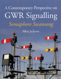
For over 150 years Britain's railways have relied on a system of semaphore signalling, but by 2020, all semaphore signals and lineside signal boxes will be gone. A Contemporary Perspective on GWR Signalling provides a unique record of the last operational mechanical signalling and infrastructure on Britain's railway network, as it applied to the former Great Western Railway (and lines owned jointly with other companies). It also includes a comprehensive explanation of what mechanical signalling is and how it works. Beautifully illustrated with over 400 contemporary images and with detailed information from a 2003-2014 survey, this is an essential resource for anyone with an interest in the traditional signalling systems of railways in Britain. The book covers: Lineside signalling equipment - semaphore signals, brackets and gantries, and other variations. Ways of working, from Absolute Block to Track Circuit Block (TCB). Detailed coverage of the signal boxes and infrastructure on Network Rail, including routes through Shrewsbury, Hereford, Worcester, Cornwall, Chester and North Warwickshire. Diagrams of the major routes.
Das E-Book können Sie in Legimi-Apps oder einer beliebigen App lesen, die das folgende Format unterstützen:
Seitenzahl: 325
Veröffentlichungsjahr: 2015
Ähnliche
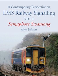


A Contemporary Perspective on
GWR Signalling
Semaphore Swansong
Allen Jackson
THE CROWOOD PRESS
First published in 2015 by
The Crowood Press Ltd
Ramsbury, Marlborough
Wiltshire SN8 2HR
www.crowood.com
This e-book first published in 2015
© Allen Jackson 2015
All rights reserved. No part of this publication may be reproduced or transmitted in any form or by any means, electronic or mechanical, including photocopy, recording, or any information storage and retrieval system, without permission in writing from the publishers.
British Library Cataloguing-in-Publication Data
A catalogue record for this book is available from the British Library.
ISBN 978 1 84797 950 6
Frontispiece: Tondu station and the route set for Maesteg, September 2006.
Dedication
For Ninette.
Acknowledgements
The kindness and interest shown by railway signallers and the resident GWR expert at the Severn Valley Railway Museum, Kidderminster.
Contents
Preface
Introduction
1 Lineside Signalling Equipment
2 Ways of Working
3 Signal Boxes and Infrastructure on Network Rail
Worcester Area
The Cotswold Line
Worcester to Hereford
Shrewsbury Area
Shrewsbury to Hereford
Hereford to Newport, South Wales
North Warwickshire
Worcester to Birmingham
Chester to Wolverhampton
Cornwall
The Absorbed Lines
Useful Resources
Index
Preface
Although this book is largely a celebration of the past it could not have been written without twenty-first-century help.
After a long period of decline and neglect the railways are vital to many people’s lives once more and it is right that the network be modernized and forward-looking.
The book has been written to appeal to the interested layperson rather than the signalling professional although grateful thanks are necessary to those people for their patient explanations of how it works.
Fig. 1 Class 66, 66 085 thunders through Craven Arms, Shropshire, heading north under clear signals on a Llanwern to Shotton steelworks working, August 2014.
Introduction
For over 150 years the safety, organization and efficient running of Britain’s railways have relied on a system of semaphore signalling controlled from signal boxes, but by 2020, we are told, what remains of our rich heritage will no longer have a part in controlling the nation’s network. This process of change has, however, been going on for around 100 years: in 1947, for example, there were about 10,000 signal boxes and in 2014 there were about 800 on Network Rail. By 2020 there will be fourteen.
Fig. 2 Looking at the jumble of signals from the Wolverhampton line towards Shrewsbury station with the largest mechanical signal box in the world at Severn Bridge Junction in the background, July 2014.
Luckily, in these islands, we have a preserved railway scene second to none and many of these railways have signalling systems that fully represent the semaphore and signal box scene that is so quickly disappearing from the national picture. The National Railway Museum at York has many signalling relics as well as the renowned Lancashire and Yorkshire Railway signalling school. In addition there is much signalling equipment in private hands and you can come across it almost anywhere.
The purpose of this volume is to present a record of the last of the operational mechanical signalling and infrastructure on our railway network as it applied to the former Great Western Railway including lines owned jointly with other companies.
Even at the outset the main lines in Britain had largely been modernised and it was a process begun in the 1960s. This has meant that large areas of the network have no mechanical signalling or signal boxes left and it has been so for some years now.
The GWR had its own way of doing things and some of that is retained to this day. Whilst most of the early railway companies sought to subcontract out the manufacture of signalling equipment, the GWR was ahead of its time in having its own signal works at Caversham Road in Reading. It was unusual in favouring the lower quadrant signal arm and persisting with that until the end of its existence on 31 December 1947. This means that the arm is normally at danger in the horizontal position (as on the title page photo at Worcester Shrub Hill), but when giving a Line Clear the arm drops down to below the horizontal. The Midland Railway and North Eastern Railways and others, which all disappeared in 1923 with the grouping of the railways into the ‘Big Four’, also favoured this style. The reason lower quadrant fell out of favour was to do with safety. Manually operated signals are usually worked by an iron rod called the down rod. The worry was that if this rod broke, a lower quadrant signal would naturally droop to show an OFF or clear indication and possibly cause an accident. It is always better if devices fail safely and it was felt a lower quadrant would not.
As originally the arms were made of wood the Great Western got round this problem by making the spectacle, or the thing that holds the lens, of heavy cast iron. This would counterbalance the weight of the arm should the down rod break and hold it at ON or danger.
In 2003, when I realised that the mechanical signalling way of life on our railways was coming to an end I started the photographic collection that has provided the material for the book. My survey eventually took in the whole of mainland Britain. This has brought us up to 2015 and material is still being enhanced and added to in the race to beat the clock.
CHAPTER 1
Lineside Signalling Equipment
Semaphore Signals
The Home Signal
The purpose of this signal could be described simply as stop or go. In the horizontal position the signal is said to be ON or stop. When the arm moves down from the horizontal by an angle of at least 60 degrees it is OFF or go.
The semaphore signal has evolved over time with operational experience and different materials used. Originally signal posts were made of wood, as were the arms. Posts since the 1940s are tubular steel and arms enamelled steel. The Western Region of British Railways continued with the steel style.
The oil lamp would originally be filled and trimmed every day, then later once a week and now they are electrically lit. The ladder was to allow access to the lamp and lens for cleaning. The post is finished off with a finial at the top, which apart from being decorative protects the timber post from the weather. Finials also appear on tubular post signals but more as decorative items.
The bottom few feet of the wooden post that is buried would be burned and charred to inhibit rot. Some wooden post signals survived into the 2000s so would have been at least sixty years old.
Fig. 3 The down platform starter at Carrog, Llangollen Railway, protecting the route to Corwen, April 2008.
The example of the wooden post signal in Fig. 3 is at Carrog on the Llangollen Railway, in April 2008. The tapered wooden post is a reproduction and the signal arm has a distinctive ‘swan neck’ shape around the lens casting. This is classic GWR of the 1920s and 1930s and now exists only on the preserved railway scene.
Fig. 4 One of the last wooden post GWR signals on Network Rail at Shrewsbury, October 2003.
Just about the last survivor of a wooden post GWR signal on Network Rail was at Shrewsbury, controlled by Crewe Junction signal box. It was still working in October 2003. It had lost its finial by this time and had replacement steel arms, as shown in Fig. 4.
Fig. 5 The ‘go’ condition displayed at Greenford East, London, April 2006.
Fig. 5 clearly illustrates a tubular post signal that is most definitely OFF or go. The lenses through which the lamp shines are red and blue as the original oil lamp would shine a yellow colour. When OFF the signal would then display a green light as required.
This is a cloistered enclave of semaphore signalling in west London which is surrounded by signalling modernity. Note the London Underground Limited (LUL) tube lines in the background. The rumblings of Crossrail are not far away.
Semaphore signals are usually operated by a series of wires and pulleys and bellcranks. A bellcrank is just a lever that lets a signal wire change direction and can amplify or diminish movement.
Fig. 6 The foot of a tubular steel signal post with the operating wires going round a pulley to operate the signal lever. There are two wires as there are two signals on this post. Worcester Shrub Hill station, July 2014.
A similar principle is employed with points. All the equipment is connected to a lever in a signal box or sometimes to levers by the lineside known as a ground frame. In Fig. 6 the lever has a counterbalance weight that can be slid up and down the lever and then locked when the optimum balance position has been found. The signal technician will need this facility to set the signals up initially.
Fig. 7 The complete signal at Worcester Shrub Hill station, July 2014.
The lever operates the ‘down rod’, the black rod going vertically upwards which operates the signal arm. If the wire breaks the signal will return to ON or stop and is therefore failsafe. Fig. 7 shows the complete signal at Worcester Shrub Hill station.
The action of a train driver who passes a signal at danger is referred to as a SPAD (signal passed at danger) and this can have dire consequences. The Paddington rail crash of October 1999 was a SPAD and the cost was thirty-one people killed and over 400 injured. It was subsequently decided that the signal involved was badly sighted. There is a section on signal sighting later on in the Introduction.
The Distant Signal
A train that is moving fast and is heavy to the tune of several hundred tons possesses momentum, and this means any change in speed can take a while to take effect. The media will often compare it to a supertanker ship.
The distant signal is placed before the home signal to warn the train driver that the next signal might say stop and the distance between the signals gives the driver time to bring the train to a stand if needed.
A distant signal in the ON or horizontal position means proceed with caution and be prepared to stop at the next home signal. OFF means the next home signal is also OFF. The distance between home and distant signals is often a function of the maximum line speed: the higher the speed, the greater the distance between distant and home signals. In confined station areas, where speeds are low, the distance can be much reduced. The distance between a distant and home signal is often several hundred yards.
The yellow fishtailed distant signal is now quite rare and most certainly an endangered species. It has been largely replaced by colour light signals even in areas where semaphore home signals are prevalent. Colour lights are much easier to see in foggy and low light conditions and are considered safer.
Fig. 8 A home and distant signal on one post. The home signal is saying proceed but the distant is saying proceed with caution and be prepared to stop at the next home signal. These signals are between Severn Bridge Junction and Sutton Bridge Junction Shrewsbury, July 2014.
In Fig. 8 the home signal is OFF but the distant is ON, meaning proceed past this signal but be prepared to stop at the next signal. This is a common means of slowing a train down when it is to take a slower line at the next junction signal. In this case the train is headed along the former Cambrian line, which is a slower-speed diverging route than straight on towards Hereford.
Fig. 9 The same home and distant signal on one post as in Fig. 8. The home signal and distant signals together indicate proceed and expect the next home signal to be also OFF, Shrewsbury, July 2014.
In Fig. 9 the train is obviously going down the Hereford line as both ‘boards’ are off. Note the modernized ladders and hoops on this Shrewsbury signal.
Some parts of the former GWR, Western Region British Railways, were hived off to other regions. Some of the area around Shrewsbury became London Midland Region from the 1960s and so other influences have been creeping in. Upper quadrant signals similar to ex-LMS designs are to be seen.
Fig. 10 Upper quadrant home and distant signals, with calling on arm below them on the same post at Sutton Bridge Junction Shrewsbury, July 2014.
The distant signal in Fig. 10 is an upper quadrant at Sutton Bridge Junction Shrewsbury but the two signals behind it on the opposite track are still lower quadrant. This distant signal is fixed at caution, meaning the next home signal nearer Shrewsbury station may be ON so proceed with caution.
These signals, which are permanently at caution, are referred to as ‘fixed distants’. This is why there is no lens in the OFF position. The signal is never OFF so it doesn’t need one.
As mentioned above, the distant would be ON to slow a train for the lower speed at a junction. The bracket signal on the right of the picture is the junction in question, with the right-hand arm for the Cambrian and the left for Hereford branch.
Before World War I GWR distant signal arms were red with the fishtail shape.
The Calling On Signal Arm
In Fig. 10 there is a smaller arm with red and white stripes below the home and distant arms. The purpose of this is to enable a train to enter a track where a train may already be standing, for example where two fairly short trains will occupy the same platform at a station. This is fairly commonplace as trains in recent years have got shorter but more frequent.
The mode of operation is to leave the home signal ON or at danger and bring the train to a stand. The signaller then sets the calling on arm to clear or OFF. This is to signify to the driver to proceed with the utmost caution.
Fig. 11 Home and calling on arms controlling the entry to Shrewsbury station platform 7 from the Crewe line. Crewe Junction signal box, Shrewsbury, July 2014.
Calling on arms are never used outside station areas where speeds are usually much higher and the required manoeuvre is not needed. Fig. 11 is a very modern incarnation of lower quadrant home signal and calling on arm.
Fig. 12 Bracket signal controlling entry to Shrewsbury station from the Chester line, July 2014.
There is a refinement to the calling on arm, using a device that can convey additional information, as shown in Fig. 12. The indicator is used to display either a C or a W character. A C tells the train driver to expect the platform to be occupied by another train further down towards the end. The W is to warn the train driver that although the platform may be clear, the track after the home signal that the platform is controlled by is blocked. This is an additional safety precaution lest the driver should overrun or pass the home signal at danger. The colloquial term for this indicator is a ‘stencil box’.
Ground Disc Signals
These signals are usually used to signal a manoeuvre across a crossover, where a train moves from one running line to the other, or to enter a siding or loop line. Loop lines are used to store trains temporarily while they are overtaken by a faster train or to quarantine a train that has broken down. Access to loops can also be by conventional running signals.
The term ground disc is universally used despite the fact that some signals are now raised from the ground to be at or near the same level as normal running signals. It does make sense that the track would be easier to follow if the signals are at a uniform height. On the other hand, there is also a view that placing these signals up with the running signals might confuse drivers, particularly at night. There is no set policy, however, and the final arbiter is always the visibility to a driver of a signal.
Fig. 13 Ground disc controlling entry to goods loop at Craven Arms Crossing, south Shropshire, August 2014.
In Fig. 13 there is a ground signal almost right on the crossing at Craven Arms, which controls the reverse entry to the goods loop. The normal way of entry is by ordinary running signals on posts – left to right in the picture. This signal enables a train to reverse into the loop. It is on the right-hand side of the track, as the driver looks back while reversing, and being on the left side of the locomotive, would be able to see the aspect. The GWR had such a device as a backing signal, and these can still be found in preservation at Bridgnorth and Bewdley on the Severn Valley Railway. They were often found together with a route indicator or cash register to signify which of several routes the train was reversing down.
The signal is wire operated and you can see the wire disappearing up to the top right-hand corner of the picture. Part-way down the wire is a steel bar, and the purpose of this is to slot into another bar at right angles which is attached to the point or turnout in question. These are detection slide bars.
This bar at right angles has slots cut into it that coincide with a slot cut into the ground disc bar. This locks the ground disc to display only the correct indication relative to the point’s position. This feature of interlocking is a universal safety feature in railway signalling and one we shall return to later.
The signal has a standard electric lamp fitting of plastic with LEDs for illumination.
Fig. 14 Double-decker ground disc signals, upper quadrant, Sutton Bridge Junction Shrewsbury, July 2014.
Ground discs can be stacked up, one above the other, as in Fig. 14; in this case the lower disc refers to the track nearest the driver and the upper disc to the one further away. This arrangement harks back to earlier days when subsidiary signals in shunting yards or station areas would be arranged one above the other. I seem to recall the maximum on one post was six signals.
Fig. 15 Black ground disc with a yellow stripe at Worcester Shrub Hill station, July 2014.
Fig. 16 Black ground disc with a yellow stripe at Moreton-in-Marsh station, Gloucestershire, September 2009.
A ground disc can even have a different-coloured disc, as in Figs 15 and 16. This is where it is required that a locomotive or train passes the disc when it is ON where there is repetitive shunting going on to avoid the signaller having to change the aspect of the disc signal every time the train approaches the disc. Railways in the past have referred to such relaxations as ‘permissive’ working. A calling on arm may be thought of this way. These permissive signals were much more common in steam days when most trains would be shunted at some point. More recently, trains are described as a ‘block’ or in sets and so shunting is much reduced and the need for such signals is consequently reduced. They are now quite rare.
Fig. 17 Elevated ground discs coming off the Chester line, Crewe Junction signal box, July 2014.
When a ground disc is not a ground disc in terms of its position it can be referred to colloquially as a disc or dolly or even a ground dolly. A signal on a post is sometimes referred to as a doll and perhaps a diminutive of doll is dolly. Anyway, elevated ground discs, as in Fig. 17, are becoming increasingly common compared with their lower altitude cousins.
Fig. 18 Elevated ground disc on a bracket signal at Par station, Cornwall, October 2004.
Fig. 18 shows a good example of an elevated ground disc at Par in Cornwall; the lamp appears to be a converted oil lamp.
Fig. 19 Rear view of a ground signal at Shrewsbury station. This signal is controlled by Severn Bridge Junction signal box, July 2014.
Another ground signal is shown in Fig. 19 and this is included because it illustrates a principle of signalling that has a wider use than just ground discs.
The pivot lug that holds the ground disc can clearly be seen, especially the vacant one halfway up the post. At the pivot that is in use there is a white, curvy plate that clearly rotates when the signal is operated. The purpose of this plate is to obscure the small rearward-facing light that shines out of the black plastic box with the cable hanging from it. This indicates to the signaller, whose signal box is off to the right of the picture, that the ground disc has operated.
Signaller feedback is important and the signaller must be told what the actual status of the equipment is, irrespective of what controls have been operated in the signal box. This curvy plate is known as a ‘backlight blinder’ or ‘backlight cover’ and is only used on signals that can be seen by the signaller from the rear. Signals that face the signaller or are out of sight altogether do not usually have this feature. With signals that are out of sight, the signaller is advised of the signal’s position by other means, which are covered later in the book.
Brackets and Gantries
Bracket Signals
A bracket signal can be described as more than one signal mounted on one central post but with separate posts for each signal. A gantry is a construction that spans at least two tracks and has at least two posts in the ground to support a bridge-like structure. As gantries tend to be bespoke to their location they are more expensive to maintain and the policy in recent years has been to replace gantries wherever possible with multiples of bracket signals.
The bracket signal is used to signal diverging routes and the usual maximum now is a total of three routes. The height of the signals relative to one another tells the train driver what the relative speeds of the diverging routes are, as the curvature of a diverging route very often requires a lower speed than straight on. In addition the actual speeds of the various routes are spelled out on lineside discs or the earlier stencil figures, similar to road speed restriction signs.
The size of the signal arm also tells the train driver the type of route for that particular branch. For example, a 4ft arm is a passenger-carrying line and a 3ft arm is for freight or goods or locomotives on their own. In GWR days a loop or goods line would have a painted white ring on the smaller arm to indicate a lesser function. These can still be seen at Bridgnorth on the Severn Valley Railway.
Fig. 20 Bracket signal at Woofferton Junction on the Hereford–Shrewsbury line, August 2014.
Fig. 20 shows a bracket signal at Woofferton Junction between Shrewsbury and Hereford, where there is a goods loop. The 4ft right-hand signal is the up passenger-carrying line towards Shrewsbury. The smaller 3ft arm is for entry to the goods loop on the left at a lower speed. You can also see the speed restriction sign for 15mph, referring to the goods loop entry. Note the most unusual finials on both posts; they look like Westinghouse Brake and Signal Company products.
Fig. 21 Triple-armed bracket signal controlling the entry to Shrewsbury station off the Crewe line, July 2014.
Fig. 21 shows the three-way bracket signal controlled by Crewe Junction signal box at Shrewsbury. The signal is located coming off the Crewe line and indicates whether the train is to go into platform 4 or 7, or the passing loop that avoids the platforms altogether. Reading from left to right it would be loop, platform 7, platform 4. The wires coming away from the girder platform are like guy ropes on a tent, there simply to steady the structure.
The backlight blinders behind the arms show up well here and are needed, as Crewe Junction box is some way behind the signal post to the left of the picture.
Fig. 22 Triple bracket signal at Worcester Shrub Hill station, November 2008.
Back to Worcester Shrub Hill station now and another three-doll bracket signal in Fig. 22. The doll on the left is for the line to Hereford via Worcester Foregate station. This is approached on a curve, which explains the lower height of the post.
The centre 3ft arm is even lower and that is because it leads straight to the locomotive sidings, which are only a little way from the station and so caution is necessary.
The post or doll on the far right is the Birmingham line out of the station and is the fastest line of the three. All the distant signals are fixed as this is in a station area and these distants do not even have spectacles or lenses, just a yellow lamp that shines ahead.
Fig. 23 Bracket signal with centre-balanced arms, Shrewsbury station, September 2005.
Fig. 23 is more of a historical piece than one containing any novelty except that the signal arms are not only wood but are centre balanced but still lower quadrant. This means that the arms are not pivoted at the ends but in the centre of the arm. This gives rise to a curious position for the blue lens. You can clearly see that the wooden arms are clinging on to their existence thanks to some steel strapping supports. Centre-balanced arms are used where space is at a premium and quite often on platforms where a full-length arm might strike a passenger when in the OFF position. Clearly visible are the bellcranks that transmit the movement of the signal wire from the signal box up through a tube to rods via the bellcranks and then to the signal arm. On the left-hand signal, which is easier to follow, the rod connected to the arm must go up to move the arm off. If you follow it through you should be able to see that the rod behind the SBJ plate must also go up to move the arm to the OFF position.
The signals control the exit from platform 7 at Shrewsbury station. The left-hand arm is for Wellington and Wolverhampton and the right for the crossovers to Sutton Bridge Junction and the Hereford and Cambrian lines.
Fig. 24 A pair of bracket signals outside Newport Park Junction signal box, South Wales, August 2006.
Bracket signals don’t always have multiple signal arms on them. In the example shown at Newport, Park Junction in Fig. 24, the signal on the right is of the bracket form because of sighting by the train driver. This is becoming a common theme – many variations in signal placing and ancillary equipment are to do with driver sighting. Both bracket signals are conventionally situated to the left of the line they serve.
Park Junction signal box has 100 signal levers.
Fig. 25 A signal sighting bracket outside Worcester Foregate station, March 2004.
A further example of a driver sighting bracket signal is the example outside Worcester Foregate Street station in Fig. 25. This seemingly rather odd configuration for double track is explained by the fact that these are two single lines. The one on the left goes to Droitwich Spa and the one on the right to Worcester Shrub Hill station. The sighting bracket to Shrub Hill also has a fixed distant on the same post. The bracket signal would normally be on the left of the track it serves but once again, for sighting reasons and ease of maintenance, the post has been placed on the right.
As these are single lines where traffic can run in either direction on either line, the line is also signalled in both directions.
Gantry Signals
Fig. 26 Gantry facing the Crewe and Chester lines, Shrewsbury station, October 2003.
Gantries have become something of a rarity, and only the one controlled by Crewe Junction signal box at Shrewsbury, shown in Fig. 26, is offered for study. It controls the movement from platforms 3 and 4 and the through line from Wolverhampton to the Chester and Crewe lines. Originally there was a semaphore doll for each possible route that could be taken and that added up to ten as recently as the 1950s. However, with the colour light ‘theatre’ route indicators this has been reduced to just three signals in all. Even the remaining semaphore signal has lost its finial, which is distinctly un-Shrewsbury-like.
The illuminated theatre-type route indicator has been around since at least the 1950s and it uses a matrix of bulbs that are selected to indicate a route in the form of a letter, for example, M for main. These are still around but in a more modern format have ultra-bright light-emitting diodes (LEDs) that form the letter display, and some have fibre-optics. LEDs have a longer service life than filament bulbs and consume less power per unit, and the same is true for fibre-optics.
Semaphore gantries are, however, making a minor comeback, with a fine example at Kidderminster station on the Severn Valley Railway.
Route Indicator
When you have more than two diverging routes a gantry or multiple bracket is needed to display all the options, each with their own arm. This is more costly to construct and perhaps confusing to a train driver. The other issue can be one of space at the trackside.
Fig. 27 Sole surviving Network Rail ‘cash register’ signal, Worcester Shrub Hill, November 2008.
Fig. 28 Rear view of the route indicator at Worcester Shrub Hill, July 2014.
A solution to this is the route indicator that is known colloquially in the signalling industry as a ‘cash register’. This is because the action of pulling a lever in the signal box raises a caption in the white-backed box below the signal arm. In the example in Figs 27 and 28 at Worcester Shrub Hill it could have offered three options – B’HAM, H’FRD or LOCO. These are abbreviations for Birmingham, Hereford or the locomotive depot. This is a historic situation in that LOCO is no longer required, and if you look carefully at the number of levers below the black caption box you will see there are now only two, for the other two destinations. The caption box was originally lit from behind by an oil lamp.
This signal is the starter at the end of platform 2, whereas paradoxically at the end of platform 1 is the full bracket array for the three destinations. Perhaps there wasn’t room for all that again on the adjacent platform. These arrays form the front cover page for this book.
These signals in this form are now very rare and the only surviving example on Network Rail is at Worcester Shrub Hill.
There had been another at Yeovil Pen Mill in Somerset but this has been replaced by a Southern Region bracket signal, as this place also lost its loco depot and so only two destinations were needed. Yeovil Pen Mill is on the route from Castle Cary to Weymouth and this had been transferred to the Southern Region in the 1960s.
These signals tended to be in lower-speed areas such as stations or shunting yards. The first recorded occurrence of their use was at Paddington station in 1909, where a six-route cash register was installed to control empty coaching stock movements into the platforms, numbered 1 to 6.
Motorized Signals
So far we have only considered signalling operation in terms of wires pulled from a lever in a signal box and then a counterbalance weight returning the signal to danger when the lever is returned. Some signals, because of distance from the signal box or other operational reasons, may have to be remotely worked by electric motor. In the earlier days, before mains electricity was commonplace, motor-worked signals and indeed points could be energized by a small generator usually referred to as a ‘hurdy gurdy’ as it had to be manually cranked. Nowadays motorized devices are mains driven and signal boxes are equipped with uninterruptible power supply (UPS), which is basically batteries that supply mains standby power through a device called an inverter. Inverters are commonly available to run mains equipment in cars and caravans.
Fig. 29 Looking towards Hereford from Craven Arms station platform. The signal number 1 is on the right and in the distance with its back to the camera, August 2014.
The first example (Fig. 29) of a motorized signal is signal number 1 at Craven Arms Crossing signal box, which, although it is a home signal, is 1,211yd (1,107m) from the signal box. The signal is pulled with a conventional lever, which operates an electrical switch that drives the motor to pull the signal off for an approaching train. When the train has passed, a sensor at the trackside returns the signal to the danger position automatically. The signaller still has to return the signal lever back in the frame manually.
Fig. 30 Gobowen down platform starter for Chester. Note the motor on the post above the signal arm. Gobowen North signal box is across the crossing, August 2004.
Fig. 31 Side view of Gobowen North signal number 4 (GN4), November 2004.
Next we go north to Gobowen near the Welsh border between Shrewsbury and Chester. In this example this signal is motor driven by a motor up the post, even though Gobowen North signal box is across the road.
This was because the proximity of the crossing was thought to be a hazard to normal signal wires and there was a fear of vandalism at this location.
Fig. 32 Motor-worked home signal, Worcester Tunnel Junction signal box, April 2005.
Worcester Tunnel Junction signal box controls the home signal on the up main line towards Shrub Hill station, shown in Fig. 32. This time the motor is at the bottom of the post. This is unusual in that the signal box is just behind the photographer so it’s not a distance thing. This is more likely to be related to automatic operation to safeguard the entry to the station.
Banjo Signals
Fig. 33 Banjo disc and calling on arm at Worcester Shrub Hill station, July 2014.
In an environment where regular-sized arms are not appropriate and the background clutter would make a conventional signal arm difficult to spot by a train driver, there is a large 32in (81cm) disc signal available, as in Fig. 33. This is another area where Worcester Shrub Hill can claim to have the only working example left on Network Rail. This signal controls the up platform movements. Note the half-size calling on arm below is not striped but simply inscribed CO instead. This lettering of signal arms harks back to earlier days. Just two wires operate the 32in banjo disc and the calling on arm.
Originally the track layout was more complicated, as can be seen from the redundant bellcranks on the wall at Worcester Shrub Hill station.
The Sighting of Signals
A good deal of time and energy is spent making sure that train drivers can see signals clearly and in good time to take action. We’ve seen some of it already.
Very often a signal position is changed or additional equipment is employed to help sighting after train crews have commented on their view, or lack of one, of the signals.
Fig. 34 Bellcrank and wire detail from the banjo disc and calling on arm Worcester Shrub Hill station, November 2008.
Fig. 35 Evesham’s E33 signal on the wrong side of the tracks, with lower-mounted arm and smaller-size 3ft arm, March 2004.
Where driving is on the left, traffic lights or road signals are commonly on the left, and so it is with railways unless there is a reason to change it. In Fig. 35 we have a home signal – in fact the plate on the post tells us it is Evesham’s signal number 33 – and the signal is halfway down the post, is smaller and has a centre-balanced arm as opposed to side-mounted. Furthermore, the signal refers to the left-hand side tracks and yet is positioned by the right-hand side track.
All these differences are to aid sighting of the signal by a train driver.
Fig. 36 The reason for Evesham’s E33 signal being engineered so distinctively can be seen – and so can the signal, March 2004.
In Fig. 36 we can see the reason for all the changes. The view is from the train driver’s approximate position and the position of the road overbridge explains all. If the signal was sighted on the left and at a typical post height the driver would never see it. The red and white chequerboard on the bridge arch is to warn of limited clearance.
Fig. 37 A pair of home signals with sighting boards coming off the Chester line into Shrewsbury station, July 2014.
Sometimes it is not necessary to move the signal to the other side of the track or the arm down the post but just highlight the view, as the background may be such that the signal view is lost in clutter and therefore difficult to see. Sighting boards are sometimes used to highlight the background to a signal’s position. Two such signals fitted with sighting boards on the approach to Shrewsbury station from Chester are shown in Fig. 37. The signals control access to the up main goods loop (left-hand signal) and platform 7 (right-hand signal).
It used to be commonplace to whitewash a road overbridge that was directly behind a signal to improve sighting. That is not so common now.
Fig. 38 A centre-balanced starter signal at Liskeard, Cornwall, March 2004.
In the next example a special installation is necessary due to the nature of the station shelter and the sheer rock face behind the platform. Fig. 38 features the up starter at Liskeard station in Cornwall; ‘up’ here refers to towards London, whereas ‘down’ is towards Penzance. ‘Starter’ means it is the entry point to the next block section (seeChapter 2). The signaller cannot lower this signal until permission has been granted from the next signal box along the line.
This lower quadrant signal is shown OFF. It is made of wood and so is a rarity.
Fig. 39 A tall bracket signal approaching Craven Arms in the direction of Hereford, August 2014.
These signals at Craven Arms in Fig. 39 have had exceptionally long posts fitted to the bracket so that the train driver can see the signals above the bridge that the photographer is standing on. The signals control the entry to the down section at Craven Arms and the main line is pulled off for a class 175 Coradia DMU, which is heading for the Hereford direction. The smaller 3ft arm on the left is to control entry to the down goods loop.
Fig. 40 A sighting board and calling on arm from the rear at Worcester Shrub Hill station, July 2014.
Another home signal plus sighting board is shown in Fig. 40, this time from the rear together with a calling on arm at Worcester Shrub Hill station, the up main signal from the Birmingham route.
Banner Repeater
Another device to aid the sighting of running signals is a different type of signal. The banner repeater is used to repeat the aspect of a signal that is too difficult to see until it’s too late. It gives an advance warning of what is to come and is often found on lines of severe curvature, where making the posts taller or shorter and so forth would not solve the problem.
Fig. 41 Banner repeater on platform 4 at Shrewsbury station, September 2005.
Fig. 42 Rear of the banner repeater on platform 4 at Shrewsbury station, September 2005.
Fig. 41


