18,49 €
Mehr erfahren.
- Herausgeber: Crowood
- Kategorie: Lebensstil
- Serie: Crowood Metalworking Guides
- Sprache: Englisch
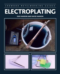
Electroplating in the home workshop can seem a daunting task due to the range of chemicals, the unfamiliar processes and the underlying chemistry involved. However, the results of a well-cleaned item and a well-maintained electrolyte are overwhelmingly impressive and, compared to sending parts to be industrially electroplated, are very cost effective. The practical advice given in Electroplating will provide you with the confidence and ability to create an electroplating tank of your own. This book will guide you through each of the processes and the equipment needed to start your own plating system and, alongside detailed step-by-step photographs and diagrams, provide instructions on their most effective use. It covers: the history and scientific basics of the electroplating process; types of electroplating metals and their function and applications; formulations and ingredients for electroplating solutions; advice on selecting the best equipment to use depending on tank size; detailed processes of cleaning and its vital importance to the final results and finally, safety information including personal safety and the correct disposal of chemicals.
Das E-Book können Sie in Legimi-Apps oder einer beliebigen App lesen, die das folgende Format unterstützen:
Seitenzahl: 276
Veröffentlichungsjahr: 2019
Ähnliche


CROWOOD METALWORKING GUIDES
ELECTROPLATING
DAN HANSON AND DAVID HANSON
THE CROWOOD PRESS
First published in 2019 by
The Crowood Press Ltd
Ramsbury, Marlborough
Wiltshire SN8 2HR
www.crowood.com
This e-book first published in 2019
© The Crowood Press 2019
All rights reserved. This e-book is copyright material and must not be copied, reproduced, transferred, distributed, leased, licensed or publicly performed or used in any way except as specifically permitted in writing by the publishers, as allowed under the terms and conditions under which it was purchased or as strictly permitted by applicable copyright law. Any unauthorised distribution or use of this text may be a direct infringement of the author's and publisher’s rights, and those responsible may be liable in law accordingly.
British Library Cataloguing-in-Publication Data
A catalogue record for this book is available from the British Library.
ISBN 978 1 78500 514 5
Disclaimer
Safety is of the utmost importance in every aspect of metalworking. The practical workshop procedures and the tools and equipment used in metalworking are potentially dangerous. Tools should be used in strict accordance with the manufacturer’s recommended procedures and current health and safety regulations. The author and publisher cannot accept responsibility for any accident or injury caused by following the advice given in this book.
Contents
Introduction
1 History and Basics
2 Types of Plating
3 Tank Plating: Material Composition
4 Electroplating Tank Set-up
5 Cleaning and Preparation
6 The Electroplating Process
7 Common Problems
8 Post-Plating
9 Safety
References
Index
Introduction
‘Electroplating is the deposition of metal, from an electrolyte onto an electrode. In general, all electroplating systems are made from three elements, the anode and cathode, collectively called electrodes; the electrolyte, a water-based solution containing metal ions; and an electric circuit with a power supply to create and allow a flow of electrons. These simple elements can be brought together to create a system capable of not only restoring and decorating objects, but also make them functional and able to withstand the pressures and stresses of many engineering applications.
While many forms of electroplating exist, this book will focus on tank plating. This process can be scaled to meet the needs of large industries or to be performed on a bench in a workshop, making it ideal for the DIY enthusiast looking to restore worn and rusted parts of an old motorcycle, or to small batch jewellery manufacturers. In fact, there are countless applications in which electroplating can be employed. The earliest experiment into electroplating was performed as early as the late 1700s, where an Italian scientist plated gold onto two silver disks. Chapter 1 will cover the development of the history of electroplating as well as covering the scientific principles that underpin the process; the movement of charged particles through the system.
There are numerous formulations of electroplating electrolyte and the most common of these will be covered in Chapter 3. The most common and the most functional electrolyte is that of Watts nickel. It is an acidic solution containing nickel salts in the form of nickel chloride and nickel sulphate, with the addition of boric acid and a few other additives to aid with the brightness and uniformity of the plated nickel deposits. This nickel solution has many different variations for many specific applications. In many circumstances, more than one metal layer will be deposited onto an object. Multilayer plating is common in engineering applications or in the conservation of precious metals for the creation of jewellery. An ideal metal for an underplate is copper. Not only is an acid copper electrolyte cost-effective, it has great throwing power and conductivity, meaning that it can fill in imperfections and create an appealing finish. Copper also has great mechanical properties, ductility and thermal and electrical conductivity, making it more appealing. An electrolyte that is used a lot in the restoration of fastenings and other mechanical components is zinc. This is a favourite among home electroplaters. Its cost-effectiveness combined with its ability to give a range of finishes and the ease of use make it an ideal starting point for any electroplating enthusiast.
After safety, which will be covered in the final chapter, cleaning and preparation are the most critical steps in electroplating. Soils, the collective term for dirt, rust, oxides, oil and any other material that is not part of the base metal, is the enemy. Any soils that remain on the surface of an item when it is being electroplated will cause problems. These are most commonly seen as blistering, peeling and burning. Problems such as these as well as electrolyte and operating problems will be covered in Chapter 7. Chapter 6 will focus on cleaning itself and the various methods that can be used. The most effective cleaning method is that of electrocleaning; the use of electricity and electrolysis make the removal of unwanted oxides and paint easy. In this process, the work (the part to be cleaned/plated) is immersed in a cleaning solution and then made either the anode or cathode, positive or negative, in the electric circuit. Once current is applied, bubbles form on the surface of the metal and remove soils. For many items, multiple cleaning methods will be needed to prepare the surface ready for electroplating. It is always worth spending extra time and effort on cleaning and preparation to avoid problems and for the best finish.
Be safe. Some chemicals used can be extremely hazardous, so take extra care and precautions and always read the material safety data sheets. Also, we strongly advise that you follow the safety information provided in Chapter 9 and find additional material from the further reading listed in this book if you are still not confident. The information contained within this book is intended to give you the confidence to perform your own experiments with electroplating, from creating electrolytes safely to achieving pristine, clean surfaces and quality final pieces. Throughout the book there are text boxes with hints and tips to help with your electroplating experience; these are little bits of information we have gathered and learnt from trial and error and from the experiences of numerous home platers.
1 History and Basics
Electroplating has been developed from an art form to an almost exact science, all driven by the developing needs of industries. Aerospace and microelectronic applications of electroplating used frequently today are beyond the comprehension of the first experimenters of electrodeposition. The first experiment involving the electrodeposition of metal is a little uncertain. It is widely accepted that the first experiment was performed in 1772 by an Italian professor of experimental physics, Giovanni Battista Beccaria [1]. His experiment used the charge from a Leyden jar, an early capacitor consisting of a glass jar and layers of metal foil, to decompose metal salts and deposit metal.
The development of electroplating has closely shadowed the development of electricity production with the first published experiment in gold plating occurring five years after the creation of Alessandro Volta’s, Voltaic pile. This early battery was used in the gold plating experiment by a colleague of Volta, Luigi Valentino Brugnatelli, in which the charge from the pile was used to facilitate the electrodeposition of a thin layer of gold from a solution onto two silver medals. Brugnatelli described how he had
‘recently gilt in a perfect manner two large silver medals, by bringing them into communication, by means of a steel wire, with the negative pole of a Voltaic pile, and keeping them, one after the other, immersed in ammoniuret of gold newly made and well saturated.’ [2]
No substantial progress was made to the development of electroplating due to the inadequacy of the Voltaic pile and other battery systems. There were, however, numerous scientists that were intrigued by electrochemical reactions (including electroplating), one of them being Michael Faraday. Among his other important discoveries and theories were his laws of electrolysis. After a few major experiments and the invention of the volta-electrometer, Faraday’s results had implied two laws:
1 The chemical deposition due to flow of current through an electrolyte is directly proportional to the quantity of electricity passed through it.
2 When the same quantity of electricity is passed through several electrolytes, the mass of the substances deposited are proportional to their respective chemical equivalent or equivalent weight.
where M is the molar mass of the substance, F is the Faraday constant and z is the valency number of the substance. Faraday’s first law can therefore be expressed as:
This equation will be important later where it is used to work out the thickness or time of deposited material. These laws, along with a series of experiments, had given a sound qualitative and quantitative foundation for electroplating.
Invented in 1836 by British chemist, John Frederic Daniell, the Daniell cell [3] (a development of the Voltaic pile that allowed for a sustained, constant electrical output) provided electroplating with a suitable source of current for further experimentation, allowing for a more uniform coating of metal. Many scientists quickly took to experimenting with the new cell, one of whom was George Richards Elkington, who filed one of many Elkington patents on ‘An Improved Method of Gilding Copper, Brass and Other Metals or Alloys of Metals’ [4][5]. George, along with his cousin Henry, later filed many patents on electroplating. They were first interested in it as a technique to replace the hazardous gilding process, substituting these chemicals with materials that were less poisonous and easier to handle.
Later in their career, the Elkington cousins formed a partnership with John Wright, who discovered that gold and silver could be dissolved in potassium cyanide for use as an electrolyte in electroplating. A patent was hastily written and granted on the use of a cyanide electrolyte for gold and silver. The Elkingtons were granted further patents and eventually had great commercial success electroplating expensive-looking silverware and precious metals for very low cost.
Scientists in Russia, namely Moritz Hermann von Jacobi and Maximilian Herzog von Leuchtenberg, also took great interest in the Daniell cell. Initially, Jacobi repeated Daniell’s experiments, finding similar copper deposits mentioned in the first experiment. He then replaced the cathode with an engraved printing plate. The engraving was removed and Jacobi was left with a metal object that had a clear impression of the plate. This is now known as an electroform. Jacobi continued his work and reported his findings to the Academy of Sciences in St Petersburg, describing it as ‘galvanoplastik’, translated as electroforming. Jacobi was an advisor to Leuchtenberg who went on to create the St Petersburg Electroforming Company, one of the largest at the time with more than 800 employees. The company started off by producing electroforms for printing papers, but later went on to reproduce artworks by taking electroforms of statues and sculptures.
As the Industrial Revolution expanded from Great Britain to the rest of the world, the knowledge of electroplating began to broaden. Other types of plating processes, driven by specific manufacturing and engineering applications, were adapted for commercial usage. These included bright nickel plating, brass plating, tin plating and zinc plating.
After growth of the electroplating process in the Industrial Revolution, many new material advances were made. The scientific and mathematical models were developed to help to explain how the process worked and a few improvements were made in direct current power supplies, manufacturing methods and electrolyte solutions. The cyanide gold and silver solutions changed very little until, due to a surge in the electronics industry, the hazardous cyanide baths were mostly replaced with safer acid baths[6].
Today, the growing applications for the electronics, car and aerospace industry are beginning to push the boundaries of the structure of electrodeposited metal. There have also been, justifiably, further safety regulations, laws on emissions and disposal, chemical advancements and requirements for the entire electroplating industry. Many of the chemicals that have been used for generations are now being phased out in preference for safer and less detrimental alternatives to protect workers and the environment.
Faraday’s Nomenclature
It is interesting to know that Faraday, in correspondence with William Whewell [2], established the nomenclature associated with electroplating including the terms anodes, cathode, anion, cation, electrolysis and electrolyte.
WHAT MAKES A PLATING TANK?
The components of a plating tank, or in more general terms an electrolysis cell, consist of three main parts: the electrolyte, electrodes and electric circuit.
Electrolyte
The electrolyte is almost always aqueous where water is the solvent. Creation of an electrolyte solution would start with distilled, deionized (DI) or reverse osmosis (RO) water.
1.1: 1. Electrolyte – the plating solution containing the dissolved metal ions is the material that connects the two electrodes. It is almost always aqueous (water-based) and has many other additives to help with the plating process. 2. Electrodes a. Anode – the positive electrode, usually made from the same metal, which is dissolved in the electrolyte and is used sacrificially. It can sometimes be an inert or insoluble material to complete the circuit. b. Cathode – this is the negative electrode and the part to be plated. It can either be a metal or another material coated with a conductive layer. 3. Electric circuit – the electric circuit consists of a source of direct current (a power supply), to deliver current to the plating tank, an instrument for the regulation of voltage and current and possibly ammeters and voltmeters to measure them.
These types of water are similar in that the processes remove ionic impurities, but they are not interchangeable. Distilled water is demineralized water that has been purified through distillation. DI water is created by running water through an electrically charged resin. The ions in the resin react with ions in the water to produce more water. DI water is quite sensitive and will start to react with air as soon as it comes into contact. Carbon dioxide from the air will dissolve and react with molecules into the water, forming hydrogen ions and bicarbonate. It also does not remove any impurities in the water, only charged particles. Diffusion is the movement of molecules from an area of high concentration to an area of low concentration until a thermodynamically favourable equilibrium is reached. Osmosis is a special case of diffusion where the molecules are water and the concentration gradient is a semipermeable membrane. The best type of water for an electrolyte would be RO water.
Ionic crystals are the next component in the creation of an electrolyte solution. These usually take the form of a metal salt lattice; MA is an example we will use here, where M is the metal and A is the salt. The salt can also be written as a product of two ions Mz+Az-, where z is the valency (number of extra/missing electrons) of the ion. When mixed with water, the ion-ion bonds in the lattice of the crystal will break and the ions will interact with water to become hydrated. This can be represented by the equation:
Mz+Az-+ 2H2O→Mz+H2O + Az-H2O
The dissolved ions become the carriers of the current in the electrolyte and are attracted toward the electrode of opposite charge to the ion itself.
Additives are another main constituent of an electrolyte. They aid with several different variables; stabilization, pH, crystal growth, metal deposition and removal and ion transportation. The main types of additives are brighteners, levellers and carriers.
Brighteners are molecules that are plating accelerators, grain refiners and/or micro-levellers. They are used to make the new metal surface look brighter; this occurs through grain refinement (the reduction of metal crystal size) and micro-levelling. Carriers work on the anode instead of the cathode. They help create and maintain a diffusion layer that regulates the flow of metal ions from the anode and, ultimately, to the cathode. Levellers are strong plating inhibitors, which co-function with brighteners to reduce metal growth at corners, peaks and edges by increasing the electrical potential (amount of work needed to move a unit of charge from one point to another) in those regions. If a metal layer is not forming uniformly on the cathode, the atoms can start to build irregular shapes (seeImages 1.2a to d). The levellers work to even out, to level, this irregular growth and create a more uniform layer.
1.2a: The change in shape of the metal surface is coupled with a change in the current density (the amount of current flowing per unit area) and therefore electric potential will change in this area.
1.2b: The levellers are attracted to this change in potential and inhibit the attachment of more metal ions in this region, forcing them to be deposited elsewhere.
1.2c: As the metal deposits level out, the potential decreases and the brighteners are no longer attracted.
1.2d: The brighteners are free to drift away to another area of high potential.
Cathode
The cathode, as mentioned above, is the part to be plated, and is often called the ‘work’. Prior to electroplating, the cathode will have gone through a rigorous cleaning process to prepare the surface, removing soils and impurities and activating the base metal.
1.3: The cathode is connected to the negative of the power supply and attracts positively charged particles called cations. These particles are the metal ions, Mz+, that react at the cathode to form metal atoms and other products to create a new surface layer in a reaction called reduction.
Anode
The anode is the electrode that is connected to the positive end of the circuit. It is made from the same metal as the ions in the solution and is used to replenishment these ions when they are deposited from the solution onto the cathode. In some systems, inert anodes, such as carbon and platinized titanium (titanium anodes with a thin layer of platinum on the surface), are used.
1.4: As the metal ions in the electrolyte are used up, more ions are stripped from the anode in a process called oxidation. In this process electrons are lost, and metal ions are created. Occasionally, inert anodes may be used.
The External Circuit
The most important part of the external circuit is the power supply. In all applications of electroplating, this must be able to deliver direct current, DC. The ions in the electrolyte move due to the electric current (and therefore electric field) supplied by the power supply. The metal ions (cations) flow with the electric field, toward the cathode, and the salt ions (anions) flow in the direction of the electrons, against the electric field, toward the anode. For a metal layer to be formed there must be a net migration of metal ions in the solution toward the cathode. With an alternating current, there will be no net ion flow; the same number of ions will join the cathode as the amount that leaves the cathode. This is because the electric field direction is oscillating over time. There is a plating technique called periodic current reversal that may seem comparable to using an alternating current, however, the net migration is still high as the amount of time the current is reversed is proportionally much smaller than when it is in the correct direction.
As part of the circuit, there must be an instrument that will be able to control the current. This is called a resistor, variable resistor or rheostat. A variable resistor is usually a coil of wire wrapped around an insulator with a wiper that can move down the length of the coil to change the resistance and therefore current supplied to the anodes. It is useful to also have ammeters and voltmeters to measure the current and voltage respectively.
HOW IT WORKS
Electrodeposition can be summarized in three main steps:
1 Ionic migration – which happens in the electrolyte solution
2. Electron transfer – which occurs at the metal-solution interphase
3. Incorporation – which ends on the surface of the metal
When a metal ion is in an electrolyte with an applied current, it will migrate toward the cathode due to its positive charge. The ion will then attach to the surface of the cathode via the transfer of electrons and become incorporated into the metal to become part of an electroplated layer. These steps of electrodeposition can be summarized as the reduction (the gaining of electrons) of metal ions from an electrolyte to form metal atoms. The reduction reaction takes the form of this equation:
Mz+ + ze-→M
where Mz+ is the metal ion with number of charges, z, which is equal to the number of electrons e-, and M is the metal atom. This reaction can happen in two different processes, electro deposition powered by an external power source or electroless deposition. Electroless deposition, or autocatalytic deposition, involves no power supply and will be explained later. For now, we will focus on the three steps of reduction.
Ionic Migration and Electrolyte Solution
The basis of most electrolytes is water. Image 1.5 shows the constituents of the molecule as well as the locations of the atoms. The dipole moment of water molecules allows them to bond weakly with surrounding atoms, ions and molecules. When water bonds with more water molecules, water clusters are formed. These can be seen in Image 1.6. The larger and higher number of water clusters contained within a solution decreases the ability of water to conduct electricity. Due to the ionic dissociation of water (the breaking of water molecules to form hydrogen and hydroxide ions), there will always be ions to reduce the number of water clusters. The more ions in a solution, the lower the dielectric constant of water will be and the better it will be to conduct electricity. Water clusters can be broken up further with the addition of metal ions. When metal ions are dissolved into water, water molecules bond to the ions and form a hydration shell. The ion and shell then behave as one entity. When current is applied, these hydrated ions move in the direction of the current due to the electric field created.
1.5: Water is made from two hydrogen atoms and one oxygen atom, hence H2O. The two hydrogen atoms form an isosceles triangle of covalent bonds with the oxygen atom. The arrangement of the atoms in the molecule gives rise to a permanent dipole moment. A dipole is the separation of two charges of equal magnitude. The side with the hydrogen atoms is positive and the side with the oxygen atom is negative. This arises due to the way in which the electrons are shared between the atoms. Water can therefore bond weakly to other charged particles, ions and other water molecules, for example.
1.6: Water clusters form due to the dipole moment of the water molecule. The attraction force is shown by the dashed line between the positive hydrogen atoms and the negative oxygen.
Metal-Solution Interphase
An interphase is a region between two phases (types of matter) that have a different composition. In an electroplating cell, the interphase is the region where the anode/cathode and electrolyte meet. We have already talked about how, in the electrolyte, the water atoms can be attracted due to their dipole, so now we will talk about the structure of the metal surface.
1.7: The exchange of ions occurs due to the reduction of hydrated metal ions close to the surface of the metal and due to oxidation. Oxidation is the opposite of reduction, electrons are lost from a metal atom to form a metal ion and electron.
When it comes to electroplating, the metal surface of the cathode is the most important feature. The surface usually refers to the first layer of atoms, or the first few layers. In regular circumstances, the metal surface is relaxed. This term is used to express the way in which the first layer of atoms has a smaller bond strength than those in the rest of the material. This is because they are not surrounded by other metal atoms. When a metal is placed into a solution containing ions of the same metal, there will be a natural exchange of ions between the two phases, even with no current involved. This can be seen in Image 1.7. Some ions enter the solution from the relaxed metal surface and some enter the metal surface from the solution until a natural equilibrium is reached. This equilibrium can be represented by the equation:
Mz+ + ze-M
The presence of extra electrons slightly charges the metal surface and interphase, which attracts water molecules. The water has an increased concentration in the interphase and some bond to the surface of the metal.
Incorporation and Electrodeposition
Bringing together the previous sections, we will describe how the metal ions are incorporated into the metal surface and how a new layer is formed. When an external power source is applied to the circuit, the hydrated metal ions begin to move in the solution. Their charge carries them toward the cathode, through the interphase and onto the surface of the metal. As the ion moves toward to the surface, it slowly begins to lose water molecules, becoming less hydrated. When it reaches the surface, the hydrated ion reaches a half crystal position. This is where the ion loses half of its water molecules and becomes bonded to the lattice with half of the bonding energy available. This allows for diffusion of the ion along the surface to find a point in the lattice where it can have the lowest energy state; where it is the most stable. This point is known as a kink site. Here, the ion gains electrons and is incorporated into the surface.
1.8: A kink site is a gap, break or ledge in the lattice that can give the lowest energy state. The ion diffuses across the surface until it reaches the kink site, where it will gain electrons to become a metal atom that is incorporated into the metal lattice.
Lattice and Crystal Growth
As more ions follow the above process, the surface grows. It can grow in two different ways, through layer growth or crystal growth. Layer growth is the spreading of steps, or discrete layers, along the surface of the crystal. Crystallite growth occurs when crystallites are formed on the surface and are grown outwards. A coherent metal layer is formed as a consequence of coalescence of these crystallites.
ELECTROPLATING OF ALLOYS
The electroplating of alloys is the codeposition of two or more metal ions onto the metal lattice. It works in the same process as above for a single metal. The hydrated ions migrate toward the cathode where electrons are transferred, and the ions reach the surface and then are incorporated at growth sites. Alloys can often be more useful in terms of finished parts as their crystal deposits have properties that cannot be achieved through plating single metals. They can be denser, harder, more resistive to corrosion, tough, stronger and much more. When plating with alloys, there is one condition that must be met; the metals must behave, atomically, in similar ways.
2 Types of Plating
TANK PLATING
Tank plating accounts for almost all electroplating processes used in industry today. Its history, development and process have been detailed in the previous chapter. In this section, different types of tank plating will be covered; manual, barrel and rack, as well as multistage electroplating processes such as multi-layer plating, periodic reverse current electroplating, as well as why they are used and examples of their end use applications.
RACK PLATING
Rack plating, along with barrel plating, makes up the major proportion of industrial plating processes. This method of plating is both space and time efficient as many parts are placed onto one conducting rack.
The spine of the plating rack is the backbone supporting each part, it must therefore have enough strength to not only carry the weight of all the parts in the tank but also to lift and transport them. The spine must also be wear-resistant and must withstand the applied forces of prolonged usage. Usually, plating rack spines are made from copper covered in an insulating material. This material is a liquid resin, such as PVC, that is painted onto the part and then cured. Primarily, this is to help with corrosion resistance and to make the rack non-conductive where immersed in solution – if it had no resin coating then the rack would be plated over and over. Copper is used due to its low cost relative to its high conductivity. Using a less conducting material, like steel, would lead to lower electrical efficiency due to resistance-induced heat loss. Steel can be used in situations where more support is needed.
2.1: A simple rack used to zinc plate steel bolts. The spine is made from insulated copper with copper arms.
In some circumstances, the plating rack may not have arms at all and the tips simply extrude from the spine. In other cases, where extra length and strength is needed, arms are added to the spine.
2.2: A variation of a home-made plating rack, again, the spine is made from insulated copper and copper arms hold bolts for plating.
2.3: Final plating rack variation in which the spine is attached to a bus bar that is placed across the length of the plating tank.
Plating rack tips are the part of the rack that connect to the cathode, to the item to be plated. The two most common materials used for rack tips used in the electroplating industry are phosphorized brass and stainless steel. Occasionally titanium will be used but this is only in special circumstances due to the larger electrical resistance of this metal. The tips can either be fixed or replaceable; each has its advantage. Fixed tips are less expensive when first creating the rack and they can be very strong as they can be incorporated into the spine. The major problem with fixed tips is longevity. If you have a rack with ten tips and one breaks, then the amount you can plate at any time has dropped by 10%. This is where replaceable tips come in. While they may be more expensive to have, they offer complete replaceability, keeping the rack output at 100%. They also help increase the usability of the rack, allowing parts to be added and removed from the rack by removing the tip. Replaceable tips also allow for the use of different tip designs to suit the need of the parts you want to plate.
While large racks are necessary for industrial electroplating that requires a large turnover of parts, the fundamentals of rack design can be used to create small, bespoke racks for home use. As a home plater, most of the parts that you will plate will be different from each other – they will have different geometries and will therefore need to be orientated differently within the plating tank to overcome problems with low and high current density. So, each rack may have to be different. When making your own rack, there are considerations to be made:
◆ What kind of plating will be done?
◆ How many parts need plating?
◆ To what solutions will the rack be exposed?
◆ What tips do I need?
◆ How should the part be orientated to achieve the best finish?
◆ Will this design provide quick and easy racking and unracking?
An ideal rack will be the results of these answered questions.
BARREL PLATING
Barrel plating, as mentioned, is one of the two main industrial plating processes that are used in electroplating. Like rack plating, barrel plating can be replicated on a smaller scale for home use. Essentially, barrel plating comprises of a rotating barrel containing all the parts to be plated. The barrel itself is placed in sequential tanks containing cleaning chemicals, rinse solutions and plating solutions. The inside of the barrel contains numerous electrical contacts that act as cathodes. While tumbling, the various parts inside the barrel contact the cathode. These parts then act as electrical connectors themselves by conducting electricity to other items within the barrel, thus increasing the efficiency of the whole process as the entire surface of all the parts become the cathode.
The advantages of barrel plating are:
◆ Speed and efficiency: a large volume can be plated at a single time.
◆ Compact design leads to space savings and smaller tanks.
◆ Labour efficient: the work remains in the barrel as you move the barrel from one solution to the next with minimal handling compared to rack plating.


