20,99 €
Mehr erfahren.
- Herausgeber: Crowood
- Kategorie: Lebensstil
- Sprache: Englisch
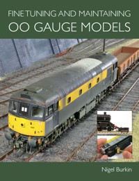
Locomotive and layout maintenance is an essential aspect of railway modelling, but one that is little understood by modellers, especially those new to the hobby or returning after a long absence. Fine Tuning and Maintaining 00 Gauge Models shows you all of the techniques required to introduce new models to your layout, run them in, fit all of the parts supplied with them and undertake repairs where necessary. It includes advice on how to carry out routine maintenance, shows the reader techniques for fine-tuning performance and discusses the important issues surrounding conversion to the finer scales. Chapters include: running in new models; fitting factory-supplied parts; rolling stock and locomotive wheels; mechanical enhancements; simple enhancements; keeping the layout running smoothly; ongoing maintenance and repairs. 00 gauge is one of the most popular gauges within the hobby and this book should have wide reaching appeal. Supported by 415 superb colour photographs and detailed instructions.
Das E-Book können Sie in Legimi-Apps oder einer beliebigen App lesen, die das folgende Format unterstützen:
Seitenzahl: 259
Veröffentlichungsjahr: 2014
Ähnliche


FINE TUNING AND MAINTAINING
OO GAUGE MODELS
Nigel Burkin
THE CROWOOD PRESS
First published in 2011 by The Crowood Press Ltd Ramsbury, Marlborough Wiltshire SN8 2HR
www.crowood.com
This e-book first published in 2014
© Nigel Burkin 2011
All rights reserved. No part of this publication may be reproduced or transmitted in any form or by any means, electronic or mechanical, including photocopy, recording, or any information storage and retrieval system, without permission in writing from the publishers.
British Library Cataloguing-in-Publication Data A catalogue record for this book is available from the British Library.
ISBN 978 1 84797 853 0
CONTENTS
INTRODUCTION
CHAPTER ONE: RUNNING-IN NEW MODELS
CHAPTER TWO: FITTING FACTORY-SUPPLIED PARTS
CHAPTER THREE: LOCOMOTIVE WHEELS
CHAPTER FOUR: MECHANICAL ENHANCEMENTS
CHAPTER FIVE: SIMPLE ENHANCEMENTS
CHAPTER SIX: KEEPING THE LAYOUT RUNNING SMOOTHLY
CHAPTER SEVEN: ONGOING MAINTENANCE AND REPAIRS
USEFUL ADDRESSES
INDEX
INTRODUCTION
Scale modelling covers a whole host of different disciplines including aircraft, ships, cars and military subjects. However, there is little to match railway modelling in its scope for authentic operation and the added dimension of movement and control made possible by the transmission of electrical current through the running rails to a locomotive. This concept in the hobby is quite old, but one that has seen much refinement in the development of Digital Command Control (DCC) and other refined operating systems in recent years.
It is this ability to introduce realistic operation to railway modelling in addition to the activities of building, construction and landscaping that attracts so many people to the hobby. Unfortunately, operations depend on a number of other factors. One of those is the transmission of electricity to a locomotive so it can be powered. Another is the sheer number of delicate components involved in turnout control, locomotive operation, couplings, lighting, digital sound and rolling stock. All of these rely on standards to ensure that equipment is interchangeable between layouts and careful maintenance to sustain those standards so that the equipment works reliably time after time. Without the application of reliable standards and maintenance of equipment, scale operation to match the accurate appearance of model trains would not be possible.
This book is all about achieving the best possible and reliable operation of OO gauge model railway locomotives and the layout environment they require to run.
It is possible to make simple detailing enhancements to an off-the-shelf model with minimal outlay, as demonstrated on this model of a Class 47 by ViTrains.
The importance of wheels and how to use wheel conversion kits is covered in the book, such as those used to convert this Bachmann Class 66 locomotive to EM gauge.
Steam locomotives such as this Hornby Southern Railway T9 are described in detail, including how its mechanism is constructed.
The objective of the techniques covered is illustrated in this photograph of two Heljan Class 33s working smoothly in multiple on my fixed home layout, and providing operation and performance that looks like that of full-size railways.
A subject little understood by modellers, especially those new to the hobby or returning after a long absence, is the matter of locomotive and layout maintenance, and it is this that will be covered in this book together with information on how to prepare models for smooth and reliable operation on the layout. Topics include how the internal workings of the model locomotive actually function, how to keep wheels clean, how to maintain the layout for reliable running and methods for preparing a brand-new model for operation with the rest of the fleet.
All of these techniques are designed to achieve the best possible results where many compromises are needed in order to make everything work smoothly. It is unfortunate that the most common causes of problems with a model railway are dirt or inadequate lubrication, and many models are returned to the model shop for warranty repair that only need routine cleaning and lubricating in order to put them back into reliable service.
With more than twenty years’ experience of operating a model railway of one sort or another, I have gathered together many different techniques for keeping my models running reliably, especially those that are getting a little long in the tooth. All the techniques I use regularly on both my exhibition layouts and my fixed home layout are described within these pages. I hope they will help you to achieve the ultimate goal of an exceptional model railway because operations are a major part of why we are all involved in this fascinating hobby. I also hope that it helps modellers setting out in the hobby to avoid the common pitfalls with regard to running-in new models correctly and then looking after them properly once they’re in service on the layout.
In the preparation of this book I would like to acknowledge the kind support and practical assistance with models and equipment offered by Simon Kohler of Hornby Hobbies Ltd and Dennis Lovett of Bachmann Europe Plc.
CHAPTER ONE
RUNNING-IN NEW MODELS
Running-in turns are a common feature of full-size railway operations where new locomotives or those that have been overhauled at a works are tested for defects. A second locomotive may be in attendance, and this was the case with this turn from Glasgow to Carlisle where a recently overhauled Class 90 electric locomotive was accompanied by a Class 47. Carlisle, January 1994.
INTRODUCTION
Railway modelling is enjoying the introduction of new locomotive models equipped with superior mechanisms and electronics that deliver a superb performance unheard of even as little as ten years ago. Fuelled by demand for better performance and superior detailing, companies such as Hornby, Bachmann and ViTrains are delivering standards close or comparable to those enjoyed by modellers in continental Europe and North America.
Yet how many modellers take the time to ‘commission’ their new models before placing them in service on a layout? After all, the full-size railways operate commissioning trials and running-in turns for all manner of new equipment before it is placed in service. As model locomotive mechanisms become more sophisticated, running-in becomes more important to identify defects, to check if the locomotive will perform satisfactorily on your layout and to see if it needs repairs under warranty. This chapter looks at running-in and what you might expect to find under the bodyshell when you first take a look inside the model. The following points are important with regard to introducing new models to the layout and how to achieve trouble-free operation:
•
Workbench tools and equipment.
•
Lubricants and cleaners.
•
First inspection.
•
Why instruction leaflets are important.
•
Running-in techniques.
•
Test running – looking for problems on the layout.
•
What’s under the body – parts and components explained.
•
What to do when something goes wrong.
WORKBENCH TOOLS AND EQUIPMENT
Experienced modellers gather a wide range of tools and sundries to assist with the maintenance and repair of locomotives and rolling stock. Running-in tests of new models require some important materials and a selection of general modellers’ tools so that a model can be lubricated, cleaned and adjusted with the bodyshell removed from the chassis.
Some sophisticated devices are available to assist with the process of running-in a new model, including combined loco testing and rolling road units (Gaugemaster and Hornby) or simple rolling road saddles (Bachrus, DCC Concepts and N Brass Locomotives) that can be placed on track. In both cases, such devices provide static testing facilities for new and existing models.
I have the following tools and materials to hand when working on new models straight from the box:
•
Jewellers’ screwdriver set for use with crosshead and slotted screws.
•
Fibre scratch pencil.
•
Cotton buds (Q-tips).
•
Cotton cloths for cleaning.
•
Fine-nose pliers for making fine adjustments.
•
Tweezers for picking out fluff and to hold scraps of cloth for cleaning in tight spaces.
•
Solvent fluid suitable for cleaning, such as isopropyl alcohol (IPA).
•
Fine lubricating oil formulated for use on plastic models.
•
Fine ‘low shear’ lubricating grease.
•
Rolling road saddles and suitable track or a rolling road unit.
•
A power pack that delivers a controlled 12v DC supply.
•
Leads with crocodile clips for easy connection to track.
LUBRICANTS AND CLEANERS
During the running-in process, the mechanism will bed gears and bearings into place. The lubricant applied to them at the factory when the model was first assembled is an important factor in this process. No matter how fine the mechanism is straight from the box, lubricant may dry out in transit and may need to be reapplied before the model is operated. Some manufacturers suggest that light lubrication is needed before a model is operated for the first time. This is one reason why instruction leaflets should always be read first in order to see if there is any warranty requirement for lubrication before operation.
There are several choices of lubricant suitable for plastic models with paint finishes. Take care to select only those that are ‘plastic safe’ and stick with brands such as Carr’s and Hob-e-Lube, which are specially formulated for use in plastic models. Carr’s offers a fine lubricating oil based on silicone technology, which is designed to be of low viscosity but will not creep into places it is not wanted. The same brand includes a silicone grease that has a low shear strength for minimum resistance and high retention, which prevents it from flying off gears and other rotating components. It is formulated for gears with a sliding action, such as worm gears, and those that are not enclosed. Both lubricants are suitable for treating model locomotive mechanisms produced by today’s mainstream manufacturers.
The Hob-e-Lube range, although more commonly used in North America, is also available in the UK. The range is ideal for painted plastic models which it will not degrade. Like all lubricants, it is designed to work with close tolerance mechanisms with low friction, high retention and low creep characteristics. Of the range of seven lubricants, the ‘Ultra-Lite’ oil is suitable for very close tolerance applications such as locomotive valve gear, while the ‘Lite’ oil is developed for medium-duty applications such as axles and bearings. Gear lube is offered for use on gears, whilst the ‘Moly’ grease is formulated for gears, axles and other high-friction applications. (For further information on the use of lubrication in routine maintenance, seeChapter 7.)
FIRST INSPECTION
As exciting as buying a new model can be, you should resist the temptation to plonk it straight on your layout and run it as you would any other model in your collection. There are several good reasons for this and, as I have discovered from experience, a new model may have a hidden defect that manifests itself when run on the layout straight from the box.
That exciting moment we all enjoy in the hobby has come around once again: the acquisition of a new model for the layout.
Here’s why the instruction leaflet is so important: it is very easy to forget about packing and transit brackets that will hinder your attempt to run the model for the first time. Next stop: the workbench!
A crosshead jewellers’ screwdriver makes short work of loosening the screws that hold the brackets in place. Reading the instructions at this point is important because in this model the screws must be refitted and tightened up again.
Many new models now come complete with a small bag of details for the purchaser to fit. The Hornby Standard Class 4 (4MT) model shown here remains to be fitted with a variety of details including brake and rigging. Leave the details alone until the model has been checked and run-in.
Another Hornby steam locomotive model made to contemporary standards is this delightful Southern Railway T9 4-4-0 locomotive. Note the comprehensive instruction leaflet and transit bracket. Both should be retained in the box after the model has been introduced to the layout.
Removing the transit bracket from the Hornby T9. Many Hornby locomotives are so fitted, including its Class 43 High Speed Train power car model.
As many wheels as possible are fitted with current collection pickups, including those on the tender of steam locomotives. An electrical jumper cable and mini plug and socket arrangement are often used to connect the tender and locomotive, electrically speaking.
The Hornby T9 also comes with a variety of detailing parts, hence its rather minimalist appearance in this picture. Information on the fitting of add-on parts and nameplates will be found in Chapter 2.
A rolling road is an invaluable device for the static testing of models. This can take the form of a loco testing and running-in station or simple but precision roller units that fit to model railway track, such as these Bachrus rolling road ‘saddles’. Some of the Bachrus range can be adjusted for different gauges and some are designed to work with a scale speed reader intended for models fitted with a speed matching decoder.
A locomotive undergoes static testing on Bachrus ‘saddles’. Each wheel set sits on a single saddle, which is fitted with tiny rollers that rotate under the locomotive wheels. They also conduct electricity from the track to the wheels. A model can be properly run-in on such a static testing device.
Bachmann produces a very competent model of the English Electric Class 37 and has released various versions of it in different liveries. This model of 37 428 ‘David Lloyd George’ is equipped with 6-axle drive, a five-pole motor, twin flywheels, a decent block of weight in the form of a die-cast chassis frame and RP25 profile wheels. It was taking a turn on Bachrus rolling road saddles before being placed in traffic.
It could be as simple as a misaligned coupling, a minor fault that could cause irreparable damage to a turnout should it catch on a running rail. Or perhaps something out of alignment inside the bodyshell may work loose on the first run, binding the mechanism and causing the motor to burn out before you can reach the model or turn the power off.
A workbench inspection of the new model before subjecting the model to a couple of hours of running in a controlled environment may detect any problems early on and save a great deal of trouble. Running-in time is also used to good effect to break a model in gently by bedding in the bearings and distributing lubricant, and to see if there are any defects that may result in the need to return the model to the manufacturer for a warranty repair. After all, locomotive models can take a pretty big bite out of the modelling budget and the higher the price tag, the greater the expectation from performance. Consequently, spending some time on ‘commissioning’ a locomotive before placing it in service will deliver benefits in terms of better running and a reduction in wear and tear over time as the lubrication applied at the factory is worked into all moving parts and dirt is removed.
I have a fairly simple regime for the introduction of new models to my collection, to prepare them for fleet service on my layout and to ensure that defects are found before the model is subject to any detailing, conversion to Digital Command Control (DCC) and fitting of scale wheels. If your new model is not running well, there is little point in changing the wheels, fitting a DCC decoder or detailing it: that won’t improve performance! Most certainly, a decoder will not much improve a steam locomotive if the valve gear is bent and causing a knock in the chassis. You may think that testing should have been done at the model shop where the original purchase was made. Many models, however, are purchased by mail order and it is not safe to assume that the retailer will have tested the model before dispatch unless you know the retailer extremely well. Even if you know that the model has been tested at the shop, it is nonetheless advisable to make a thorough check and run it in when you get it home.
Certain materials are useful for cleaning and preparation including wheel and mechanism cleaner, isopropyl alcohol (also known as rubbing alcohol) suitable for cleaning excess oil and grease from wheels, current collection pickups and gears, together with model oil and grease for re-lubrication.
The first stage after removing the model from the box is to read the service leaflet before giving the model a thorough visual inspection to detect any loose parts or components that may affect its performance or could cause damage if they fell off during operation. Sometimes it may be necessary to return the model to the shop should you discover damaged detailing parts or that something is visually wrong with the mechanism. Bogie side frames and baseplates are removed so that the gears may be checked to see if there is any fluff, dirt or particles of metal that may cause wear and indifferent running. Also check that there is sufficient lubrication before you run the model. The model should be placed in a suitable cradle to protect it when inspecting the running gear and underframe.
The visual inspection continues by checking the wheels to see that they comply with accepted standards for gauge and back-to-back measurements, because some of my models are not converted to a closer-to-scale gauge so they can be operated on club layouts. This examination is undertaken with a back-to-back gauge and adjustments are made if necessary.
Once satisfied that the model is correctly gauged, power is applied to the model via leads from a simple analogue controller. This enables me to check that the wheels are concentric and that no alarming squeals, grinding or grating noises are coming from the mechanism. Such symptoms should be investigated and if they cannot be eliminated the model should be returned for repair.
In all fairness, I have found very few faults during this first inspection with locomotives I have bought over the years. However, my inspection regime has picked up the odd problem that could have developed into a frustrating and expensive issue later on. Examples of faults I have discovered on new models include:
•
Misaligned couplings on a variety of models: simple to repair but could damage track if they are allowed to droop.
•
A Hornby Class 60 with a front buffer beam fairing detached and likely to foul lineside details.
•
A Bachmann Class 08 shunter with a broken coupling rod.
•
Pickups that do not touch the back of the wheels in several cases. No juice collected from the track means no go!
•
Current pickups out of alignment to the extent they foul spokes on the driving wheels of steam locomotives, with binding of the chassis the inevitable result.
•
Obviously loose wires: simple to fix but can mean a model either does not run or the wires touch a flywheel or become tangled with a drive shaft.
•
Excessive lubrication that becomes apparent when the model is run for the first time. This is better cleaned away before moving parts throw it all over the interior of the bodyshell.
•
Missing screws.
•
Misaligned wheels that cause binding and wobbly motion.
It is unfortunate that some models may arrive with excessive amounts of lubrication in the mechanism. One of the first checks is to look for problems like this where too much grease has been applied.
Another situation where grease has been liberally applied to everything, ending up on the back of wheels and on the current collection pickups. Clearly, electrical conductivity will be seriously impaired unless the grease is cleaned away and the pickups readjusted; here they did not meet the back of the wheel either.
WHY INSTRUCTION LEAFLETS ARE IMPORTANT
Read and retain instruction leaflets provided by the manufacturers. They often show exploded diagrams of models, the catalogue numbers for spare parts and indicate lubrication points. The screw locations will be marked in place together with advice on how to remove the bodyshell without damaging fine detail. In short, they are the mini-service manual for that particular model and may provide advice for what may be a unique model. At the very least, when installing a decoder for DCC operation, the instructions will tell you what type of DCC interface socket is inside and where to find the body retaining screws and clips.
DCC onboard and digital sound locomotives will be furnished with an additional instruction sheet giving details of the installed decoder, its operation, functions and Configuration Variables setting (CVs). This too should be kept in the box or in a safe place for further reference. In short: don’t throw leaflets away!
WHAT’S UNDER THE BODYSHELL
Nervous about what you might find under the bonnet? Reluctant to take a peek at how your prized engine actually functions? You should become familiar with the workings of your models so they can be properly maintained and cleaned in order to keep the layout running smoothly. Fortunately, the days of pancake ‘ringfield’ motors and weedy drives not even capable of pulling a feather off a table are long gone, although some modellers may still have a few models equipped with such old motors left in their collections. I am no exception, having retained a number of Lima Class 73s since no improved model of this locomotive has been produced at the time of writing.
In their place, modellers are now enjoying the benefits of skew wound five-pole motors, sophisticated electronics including DCC interface sockets and sound decoders, together with a decent amount of ballast weight to optimize haulage performance. Steam locomotive collectors are seeing the end of tender drives and ringfield type motors in favour of locomotive-fitted drives connected to all of the driving wheels. Internal improvements have, fortunately, matched the considerable improvement in external and cosmetic detail, and certainly nowhere more so than in models of modern prototypes.
There is a great deal of sophistication tucked away within the bodyshell of a diesel electric locomotive model, just as in the mechanism and electronics of full-size diesel and electric locomotives. The mechanism found in new-generation models from all of the mainstream manufacturers, including Hornby, Heljan, Bachmann, Dapol and ViTrains, is very sophisticated. When first taking a bodyshell off a model, a newcomer to the hobby may be amazed at what they find, even if the service sheet offers a hint as to what is inside. The motor is usually mounted in the middle of a large die-cast chassis frame that contributes to the model’s weight. A flywheel will be attached to one or both motor shafts, storing kinetic energy that translates to inertia when a locomotive hits a dead spot on the track, carrying it as if it has momentum like a full-size locomotive: this is a simple addition to the mechanism that improves the driving experience. Flexible couplings and drive shafts transmit power to the bogies via gear towers designed with the correct ratio of spur gears to divide the movement energy over all of the axles in the bogie. It is worth noting that not all axles in a three-axle bogie are powered on some models, including Heljan Class 47s and ViTrains Class 37s and Class 47s.
Something is the cause of an intense discussion between these volunteers on the Great Central Railway as diesel electric shunter No. 3101 sits with its engine compartment doors and roof panel open. What is actually under the bonnet of our model locomotives is also worthy of a closer look.
A typical model of a diesel electric locomotive featuring a heavy die-cast chassis block and no visible moving parts. This is a Bachmann Class 45, introduced in 2009, with 6-axle drive, DCC interface socket, working running lights and a powerful, twin flywheel drive mechanism with a low maintenance requirement – but not a lot of the mechanism can be seen!
The once common practice of fitting a ringfield motor to the tender of a OO gauge steam locomotive is no longer acceptable practice: the motor, together with its drive train, is fitted to the locomotive itself.
The Hornby T9 reveals its inner workings including a five-pole motor and worm gear train driving all of the axles of the driving wheels via the coupling rods.
The result is a smooth-running locomotive with inertia and a feeling of momentum that adds to the driving experience. By having most, if not all, axles driven (the axles of each wheel set being bushed in a proper brass or phosphor bronze bearing for durability) the necessary tractive effort is provided to pull decent length trains. Electrical reliability comes as a result of the greater mass of modern-built locomotive models and the provision of electrical pickups on all wheels; even bogie wheels of steam locomotives will be fitted with pickups in some cases. All of this technical innovation helps to keep trains running without hesitation and lights flicker-free during operation.
For those dipping their toes in the world of Digital Command Control, manufacturers of OO gauge models now routinely equip the internal circuits of most models (when space permits) with an 8-pin DCC socket (to American NMRA and European MOROP NEM standards) for the simple installation of a decoder. Bachmann has introduced a 21-pin socket for which adapters are available. As a point of interest, the 6-pin interface socket has become standard for N gauge, again set out in NMRA and MOROP NEM specifications, and is also being adopted for some OO gauge models where space is too tight for a decoder designed for use with 8-pin sockets. Examples include the 2010 release of the Bachmann Class 03 shunter.
The following sequence of photographs labels the common components of models from several manufacturers of British outline OO gauge equipment that are typical of what you should expect to find today. It is to be hoped that they will help with identification of parts for maintenance purposes or when converting models to DCC. Some are now supplied with a DCC decoder, making that process easier for the inexperienced modeller. Remember, when viewing these images, that there may be some variation between production runs of a model as improvements to the design are applied.
LIMA CLASS 117 DMU AND CLASS 73
Two models likely to be found in many modellers’ collections are the Lima Class 117 DMU, a popular model for a variety of reasons (and yet to be re-released by Hornby since its acquisition of the Lima brand), together with the Class 73. The Class 117 model was equipped with a three-pole ringfield motor of varying levels of performance, but crude and difficult to control without the benefit of a flywheel to smooth out performance. However, it responds well to very good quality decoders and equally to careful fine tuning and running-in if the drive is basically sound. Not all of them were worth a second of workbench time, but in recent years an upgrade conversion for this basic type of ringfield motor has become available (seeChapter 5).
The basic mechanism in this model is simple: no circuit board, no lighting and a simple wire connection from the unpowered bogie, where current is collected from one side only. The power bogie itself has a direct connection between the carbon brush retainer and the wheel pickups that collects current from one side only, the opposite side to that on the unpowered bogie. The result is unreliability due to inadequate power supply, something that is simple to remedy by adding more pickups and wiring.
The Lima Class 73 (and other models in Lima’s British outline range) have a similar arrangement to the Class 117, although some variation in the ‘ringfield’ motor can be observed. Despite the relatively high cost of these models when on general release, the drives are crude and often unworkable. That said, if you did get a good one it was worth refining and fine tuning, because they could be beaten into submission. All sorts of ideas, some of which are now the stuff of legend, floated around about how to refine these beasts, including the use of toothpaste as a lubricant to get the noisy gear trains to settle down. In reality, the handful left in service in my collection run smoothly due more to their high mileage, careful maintenance and use of a suitable lubricant than to anything else. ‘Moly’ grease lubricant or Carr’s micro grease product is ideal for gears with a high level of sliding contact as found on this type of mechanism.
Despite the popularity of the former Lima Class 117 DMU among both modern and transition era modellers, Hornby has yet to re-release it with a new power bogie. It may be acquired second-hand, however, usually with the old ringfield motor drive that invariably needs much tender loving care to prod it into some sort of performance.
The crude nature of former Lima models is cruelly exposed when the body is removed. As can be seen, the pancake style ringfield motor is pretty rough and is the Achilles heel of this genre of models. The one in the top right of the picture is slightly different in design but has the same running characteristics and the same faults.
The typical arrangement in Lima models, the only variation between them being the number of axles in each bogie. A large lump of metal forms a crude ballast weight, while a single wire connects the unpowered bogie to the motor. (A) Motor casing; (B) ballast weight; (C) single pickup connection to the unpowered bogie; (D) exposed wire connection to power bogie pickups; (E) carbon brush and spring holder.
Very specific maintenance is required to ensure that the motor spindle does not become too dry and carbon brushes are not allowed to become too worn so that the internal retaining springs rub against the commutator.
UPGRADED FORMER LIMA CLASS 73 BY HORNBY
Hornby was quick to recognize the popularity of the former Lima Class 73 (former Southern Region electro diesel locomotive) and set to work to upgrade the underframe and replace the ringfield motor with one using a five-pole skew wound motor. The bogies were updated with NEM coupling pockets, the pickups were improved and an 8-pin NEM decoder socket included. The result is a better performing model with smoother control. However, you have to choose your decoders carefully to achieve the best performance and the model relies on traction tyres for grip. In reality, the new power bogie is a poor relation to the high technology drives being applied to other Hornby models such as those featured in this chapter and leaves the door open for the model to be further upgraded.
The format is common to all of the former Lima models re-released by Hornby: a new single power bogie and upgrading of bogies and couplings. The format has been applied to the Class 37, 55, 59 and 66 together with the Class 121 single-car DMU and Class 156 Sprinter. The same basic power bogie was also applied to the 2009 release of the Class 153 single-car Sprinter unit.
Hornby re-released the former Lima Class 73 in various liveries during 2008. Two examples are shown in this picture, both of which have had some retooling done to equip them with a new drive bogie, DCC interface socket and NEM coupling pockets.
The new chassis for the Class 73 is typical of the re-released Lima range with an upgraded motor and slightly less crude ballast weight. (A) A single motor bogie with a five-pole skew wound motor; (B) a simple clip forms the bogie pivot; (C) ballast weight; (D) DCC interface socket; (E) unpowered bogie pivot; (F) tension lock couplings fitted to NEM coupling pockets.
BACHMANN CLASS 20 (2009 RELEASE)


