20,99 €
Mehr erfahren.
- Herausgeber: Crowood
- Kategorie: Lebensstil
- Sprache: Englisch
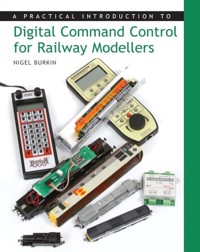
From background information on the technology itself to layout wiring; taking in decoders, hand controllers, wireless and many practical modelling projects, Neil Burkin offers a comprehensive introduction to Digital Command Control [DCC] for the beginner and experienced modeller alike.The book emphasises the benefits of DCC technology as a model railway control system and offers practical advice on the choice of systems, applying the technology to a layout, how to use it to enhance layout operations, and how it can be used to overcome practical difficulties with operations such as banking, double-heading, lighting and sound. Technical jargon is avoided and clear descriptions of each project featured in the book will remove the mystery surrounding DCC. Many of the modelling projects may be adapted for almost any modelling situation and are supported by over 400 excellent colour photographs. A comprehensive guide to Digital Command Control for the beginner and experienced modeller alike. Emphasises the benefits of DCC technology and offers practical advice on the choice of sytems. Includes practical modelling projects which are supported by over 400 excellent colour photographs. Nigel Burkin is a railway modeller with over 20 years' experience and has hundreds of magazine articles to his credit.
Das E-Book können Sie in Legimi-Apps oder einer beliebigen App lesen, die das folgende Format unterstützen:
Seitenzahl: 345
Veröffentlichungsjahr: 2013
Ähnliche


A PRACTICAL INTRODUCTION TO
Digital Command Control for Railway Modellers
NIGEL BURKIN
Copyright
First published in 2008 by The Crowood Press Ltd, Ramsbury, Marlborough, Wiltshire, SN8 2HR
www.crowood.com
This e-book edition first published in 2013
© Nigel Burkin 2008
All rights reserved. This e-book is copyright material and must not be copied, reproduced, transferred, distributed, leased, licensed or publicly performed or used in any way except as specifically permitted in writing by the publishers, as allowed under the terms and conditions under which it was purchased or as strictly permitted by applicable copyright law. Any unauthorised distribution or use of this text may be a direct infringement of the author’s and publisher’s rights, and those responsible may be liable in law accordingly.
ISBN 978 1 84797 532 4
Contents
Title Page
Copyright
Abbreviations
Dedication and Acknowledgements
Introduction
1 What is Digital Command Control?
2 Opening Pandora’s Box
3 DCC and the Layout: Wiring it up!
4 Mobile Decoders: How to Fit and Test Decoders in Locomotives and Multiple Units
5 Lighting for Locomotives, Rolling Stock and Multiple Units
6 Digital Sound and Steam
7 Setting up for Layout Operation: Train Driving on Your DCC Layout
Useful Addresses
Index
ABBREVIATIONS
DEDICATION
This book is dedicated to my ever loving and supportive wife, Sarah.
ACKNOWLEDGEMENTS
I am indebted to the following for their kind assistance with the production of this book. They have helped with practical advice, proofing for technical content or have contributed equipment featured in the projects.
Alan Murray of MacKay Models.
Stanley Kerr of MacKay Models.
Dennis Lovett of Bachmann Europe Plc.
John Jewitt of Sunningwell Command Control.
David Nicholson of ZTC Controls.
Charlotte Nicholson of ZTC Controls.
Robin Hamp of Express Models.
Ian Fowler of Gaugemaster Controls.
Diana Johnson of Tumuli Design for illustrations and photography.
A special acknowledgement to Pete Lawrenson, Chief of Security and Safety, together with Ben Hampson of Montana Rail Link for their kind assistance with my research into US locomotive operations.
And finally, to Steve Jones of Telford, Shropshire, a well-known DCC enthusiast, for dropping me into all of this DCC stuff in the first place!
Introduction
We’re all beginners at something at some stage in our lives and Digital Command Control (DCC) remains something of a mystery for some modellers (including myself at one time). Although there are many that would like to take the plunge, ‘technology’ and ‘cost’ can be barriers to adoption, even though it is becoming generally accepted as an exciting technology that brings added realism to the operation of a model railway. In this book I offer a practical introduction to DCC, accompanied by a variety of projects that can be followed and adapted to suit almost any situation.
There is little doubt that DCC is growing in popularity in the UK and the introduction of accessible entry-level and mid-range sets from Lenz, Bachmann, Gaugemaster and Hornby will help the modeller teetering on the cusp of transition to make the change. I was a convert to DCC in 2001 following a couple of years of my own brand of indecision: humming and hawing over the cost, the perception that DCC is complex and what the potential benefits may or may not be. Having made the decision to ‘go digital’ after trying it on a friend’s loft layout, in July 2001 I purchased a Digital plus Compact system by Lenz Elektronik GmbH with a handful of decoders. It was a major purchase for me and one that was very carefully considered. Five years on and I wonder what the fuss was all about!
The rationale behind my decision to ‘go digital’ needs to be explained. The construction of the first of my two (then) new exhibition layouts, Dudley Heath Yard, was followed by an intense session of wiring and control panel construction to equip it with ‘cab control’ to work with a pair of KPC hand-held controllers. The layout was a compact end-to-end design with a scenic section of 8ft supported by 4ft of fiddle yard. To obtain the operational flexibility for shunting and train operation, the layout was divided into nine sections controlled through double pole, double throw (DPDT) switches to enable dual control. In addition, there were six isolation sections for locomotive stabling. Two separate transformers were required to enable trouble-free operation with the pair of hand-held controllers and common return wiring. This project evolved into an exercise in spaghetti and soldering. Controls for points, signals and trains were grouped together on one control panel that took many weeks of careful work and testing to complete. I now realize that DCC would have saved me a considerable amount of work; but it did not save the layout – it was scrapped when its shortcomings were laid bare by the adoption of DCC and the difference in approach to operation together with layout design.
As structural work on my second and more successful layout, Platform 4a & 4b, progressed, I was faced with a smaller version of the same wiring exercise and this led to a pause in the track and electrical planning process. How could I get the much needed operational flexibility from a layout with a scenic section measuring a mere 8ft in length without resorting to so much wiring? Good question!
At about the same time, I was toying with dc lighting systems, having purchased a couple of kits from Express Models, particularly orange door lock lights for multiple unit stock. Whilst the systems work well, my research into DCC and decoders showed that there is a simpler and less costly route for locomotive and rolling stock lighting, one that would eliminate batteries and recharging from the equation, but with some different practical difficulties. All of these issues came together at about the same time and required a definitive solution before costs got out of control. Although battery- or capacitor-supported lighting systems offer constant lighting for dc (analogue) operation, the cost of installation became fairly prohibitive. I needed to increase the dynamics of the layout for exhibition use and to increase the play value for me, together with interest for the viewer. By all accounts DCC offered the most sensible solution to my layout control conundrum.
Only two wires (called the ‘power bus’) were required to get my exhibition layout up and running. Not literally, of course, because the layout was divided into sections to allow for wiring of handbuilt points with metal crossing vees and the need to feed power into the toe of such points to prevent short circuits – exactly the same as for analogue control. However, there are no cab control electrical blocks or isolation sections in the track layout and associated wiring running back to a switch panel via multi-pin connectors. The whole layout is live (think what that can do for coach lighting) and each track is supplied from two power bus wires that run the length of the layout from the back of the DCC base station. Each baseboard joint is bridged with a jumper lead containing just the two bus wires that run to tag strips. DIN plugs ensure that the jumper wires can be separated when the layout is dismantled for transport and storage. One tag strip under each baseboard provides a convenient terminal junction from which each individual running rail is supplied with current via dropper wires. It was up and running in a couple of hours and that layout operates today on the exhibition circuit, demonstrating the principles of DCC to anyone who wishes to have a go.
In the last six years DCC has completely changed my attitude to railway modelling and the way I look at layout design and concepts. When I buy a new locomotive, my thoughts turn more to making the lighting systems work prototypically, choosing the right decoder to obtain the best performance and wondering if there is room for a couple of speakers. When I design a layout, I no longer worry about the precise length of section blocks and where the control panel is going to be located.
In this book I offer a practical introduction to DCC for newcomers to the hobby as well as for experienced old hands. It is liberally sprinkled with a variety of modelling projects that can be used and adapted to suit different models. I have done all of these projects at my own workbench and made mistakes and discoveries on the way. I also feature a new layout project to demonstrate how straightforward it is to wire up a layout and incorporate some interesting equipment to enhance the operating experience.
Finally, I am keen to stress why I use DCC to operate my trains: it’s all about achieving realistic operation, as close to the full-size railway as is possible, and about having fun whilst operating the layout. Gone are the cab control and electrical block switches. Gone are the fading running lights as a model comes to a stand. The complex wiring for analogue control is consigned to history as far as I am concerned. No more console control panels that look as if they could launch a mission to Mars. When driving trains, it’s just me and the throttle, no different to the real thing.
Nigel Burkin
September 2007
CHAPTER 1
What is Digital Command Control?
Digital command control is a great way of driving and controlling your model trains using computer technology that has been adapted for the task. In effect your layout becomes a networked computer system that uses small computers in your locomotives called decoders, which respond to instructions (data) transmitted from a central processor called a ‘command station’. Each locomotive decoder responds to specific instructions sent by the command station using the decoder’s unique address: this means you can drive trains independently of each other. This is a theme I will emphasize throughout this book – it’s all about driving your trains. Nothing more than that.
After all, fun layout operation and being able to drive your trains in a realistic and flexible way is probably why you have taken an interest in DCC in the first place. It should be fun to use for all your friends and layout operators, too. When you speak to some DCC enthusiasts, however, you may be convinced that DCC is all about decoders, wiring, programming, complexity and digital data packets carried on strange alternating current waves through the track. Busses seem to come into it at times, even though train control is what we are after. Well, all of that is involved somewhere along the line – even a bus or two – but you do not need to know how DCC works to enjoy its benefits any more than you need to know how a jet engine functions in order to enjoy air travel. Some of the more complex stuff can be explored as your confidence in DCC grows, but all you will need to get started is in the box and described in the instruction manuals. DCC makes driving your model trains a fun thing to do and that’s what this book is intended to help you achieve. All of the work in wiring up a layout, fitting decoders to your engines, adjusting the settings in a decoder and installing lights, sound and steam effects is a journey to the ultimate destination of realistic train operation.
WHO INVENTED IT?
Previously made awkward by the constraints of analogue control, double-heading (also called consisting) is made possible, with a refined level of control, by DCC.
Wrapped up in the question of who could claim to be the inventor of DCC is the real one of where DCC originated in the first place and how it arrived in the world of model railways. DCC is not a model railway innovation but simply industrial machine tools technology applied to the problem of realistic model railway control. Märklin was the first company to explore digital technology of this type (there were other attempts to do so) for model railway control, under the guidance of Bernd Lenz. After Lenz left Märklin, he further developed his ideas and established the company known as Lenz Elektronik GmbH. Most DCC users rightly regard Bernd Lenz as the ‘father’ of model railway Digital Command Control as we know it today. The application really took off, however, in the USA under the auspices of the National Model Railway Association (NMRA), driven by modellers’ needs for a flexible control system that would allow multi-user operation on large layouts together with realistic multi-train operation completely unbounded by the constraints of controlling power in the rails through large panels of block switches.
Today, the far-sightedness of Bernd Lenz has ensured that certain of the system protocols essential for product inter-operability are published and available to all manufacturers, so the application of DCC is theoretically universal. Certain of those protocols are enshrined in the NMRA Standards and Recommended Practices (RPs). Not all areas are closely defined; there is much scope for individual manufacturers to demonstrate their technological flair and that leads to design differences in DCC systems that are not covered in the NMRA Standards and RPs.
Running lights remain fully illuminated on a DCC layout, regardless of the locomotive speed. They stay lit even when a train is stationary and can be independently controlled at the push of a button.
THE ROLE OF THE NMRA
The NMRA was established in 1935 as a gathering of model railway (model railroader) enthusiasts and other ‘stakeholders’ in the USA who were fed up with the wide-ranging standards from manufacturers for simple technical things taken for granted today, such as coupling standards, track scale and gauge. Prior to that, interchangeability of equipment between modellers’ layouts was difficult and that was recognized as a bar to further development in the hobby. The NMRA devised sensible Standards and RPs to ensure that equipment from one manufacturer could be run with the equipment and on the track of another using the same power packs, couplings, wheel gauge and current requirements for a given scale. The basis of this system remains valid today: to be able to run N gauge equipment from Kato, Atlas, Athearn, Bachmann and Graham Farish together on the same 9mm Peco Streamline, Kato Unitrack or Atlas ‘code 55’ track is a given – not having such compatibility is now unthinkable.
Stabling locomotives together like this requires no special electrical blocks and associated switches. Drive a locomotive up to the next and park it.
The same thinking has been applied to DCC and the Standards are recognized internationally, not just in North America. The NMRA has devised standards and RPs covering such subjects as DCC electrical, DCC communication, DCC interface design and decoder wire colour, Configuration Variables (CVs) and DCC decoder transmission. In all, there are two Standards for DCC electrical and communications protocol to ensure that the DCC signal is the same no matter what command station you use, together with nine RPs. This means that any decoder from any manufacturer will work with any DCC system provided it is at least compatible.
Recommended Practices are regarded as only slightly less vital to operation than those considered as ‘cast in stone’ in the published Standards. Deviation is only permitted if there is a good technical reason for doing so. None the less, most manufacturers strive to comply with the RPs because the NMRA describes them as being ‘only less mandatory than the Standards’ and asserts that they are present to encourage maximum levels of interchangeability.
As far as DCC is concerned, the Standards and RPs only apply to the decoder and track power side of the system. This means that the DCC signals and associated areas such as decoder wire colours, certain CVs and digital communication are covered and must comply to the published NMRA documents to achieve a conformance warrant. It does not cover the controller (throttle bus) side of DCC systems, including electrical cabling that connects hand throttles, controllers, boosters or other devices to the system (this is often referred to as the system architecture). Nor does it specify design of systems in terms of buttons, connections, type of leads, plugs, sockets and so on. That is left to manufacturers’ initiative and does mean that throttles and similar devices from one manufacturer may not necessarily work with command stations and boosters from another. The architecture for throttles differs between Lenz and Digitrax, for example, and you cannot make a Lenz throttle ‘talk’ to a Digitrax command station by simply plugging it in.
NMRA Conformity Warrants and Product Compatibility
Conformance to the NMRA Standards and RPs is a good thing because it establishes a norm for all equipment, ensuring that if you want your friend’s equipment to run on your layout, and vice versa, you can without compatibility issues. Those manufacturers that produce such products strive to maintain compatibility with the NMRA Standards and RPs because they recognize that a ‘go-it-alone’ approach would be commercial suicide. Some manufacturers, for various reasons, do not submit their equipment for NMRA conformance testing but still manufacture it to the Standards and RPs. Choose decoders and equipment that either hold an NMRA conformance warrant or are compatible and all should be fine, at least on the track side of the system that carries the digital signals. If the sharing of throttles is desired, then the architecture for the throttles must be the same (it is better to buy the same base system). But how do you know if equipment is DCC compatible or holds an NMRA conformance seal? And what is the difference between conformance and compatibility?
DCC compatibility symbol.
DCC conformance seal.
The NMRA not only writes and publishes Standards but has a programme to test products extensively for conformance to those same Standards, RPs and any applicable industry norms. This provides a measurement of conformance to the published NMRA documents and those products that comply are allowed to display the NMRA Conformance Warrant Seal. The idea is that the NMRA programme provides modellers with some assurance of inter-product interchangeability both now and into the future. NMRA conformance should be highly valued when contemplating the purchase of DCC equipment together with products that are seen as compatible with NMRA Standards, such as those produced by Digitrax and ZTC. It is important to remember that the NMRA makes no guarantees, nor is it a DCC police force. It is well known that the NMRA provides guidance for manufacturers determined to be part of the DCC community with compatible or compliant products. The whole point is to ensure customer confidence in DCC and just one rogue manufacturer could really upset the apple cart.
Drive anywhere and park anywhere are important features of DCC operation. You soon become used to it and find analogue layout operation very inflexible after running a DCC layout.
Some manufacturers choose not to subject their equipment to testing but describe it as ‘compatible’. It must be emphasized that products claimed to be compatible with the NMRA Standards and RPs have not undergone testing by the NMRA or any other organization that is currently needed for a manufacturer to claim conformance. What this means to you is that it is possible for a compatible product to work with other NMRA conformant equipment without difficulty, but some systems may not be totally compatible with other DCC products on the market. The symbol for compatibility is different to that applied to those regarded as being conformant to all applicable NMRA Standards and it refers to the ability of various products to work together. Whilst there are no guarantees, all DCC manufacturers stick to the spirit of the NMRA Standards. To deviate from them would not be helpful to any manufacturer and the DCC community quickly identifies and avoids problem products that do not conform.
You do not need to know the exact details of the NMRA Standards and RPs to operate your chosen system. However, knowing the reason for their existence is extremely helpful in making purchasing decisions. Being aware that decoders from other manufacturers should work with your system is reassuring when contemplating an investment in DCC.
WHY SHOULD I BUY INTO DCC?
Much work has been done to ensure product interchangeability, providing a measure of assurance to newcomers to DCC and a benchmark for established users to expand their systems in a coherent way. The question that many modellers ask is why should they adopt Digital Command Control technology in the first place when analogue has served them so well. What are the benefits? In other words, what’s in it for me?
Special lighting effects such as interior lighting and, in the case of modern multiple units, door warning lights can be installed and independently controlled using decoder functions.
In the introduction above I described how my decision to adopt Digital Command Control for a new layout project completely revolutionized my attitude towards the hobby. It came at a time when my personal interest was waning and the thought of sticking yet more brass details onto another misshapen plastic model was too much to bear. Suddenly a completely new way of operating my layout and detailing my models was presented to me. I now routinely enjoy a number of benefits that are unavailable with analogue control. When exhibiting my layout at train shows, I never hesitate to demonstrate to others those very benefits that prompted me to make the change.
So, what are those benefits? Even before I explored the possibilities of digital sound, simple operational features became possible without having to throw a single switch on a layout control panel. One of the misconceptions about DCC is that it is only suitable for large layouts. On the contrary, the flexibility that it introduces to operations means that many of the operating constraints of small layouts are removed. Let us explore the benefits of DCC and what they offer to operating a layout of any size.
Operational Detailing
DCC enables you to drive the train and not simply control the amount of power in the track. Put simply, an analogue controller only controls the amount of current in the track and the locomotive motor runs to the set power level. Nothing more. To obtain operational flexibility, it is necessary to fine tune the control of current in the track through banks of electrical block and isolating switches. It is possible to introduce operational sophistication, including shuttle modules and those designed to provide a degree of automated control for particular operating effects. But at the end of the day you are simply controlling the power in the track and all trains will respond to changes regardless of where they are and what device is regulating the current.
On the other hand, a DCC controller (throttle) is used to drive the specific locomotive allocated to it by keying in the locomotive decoder’s unique address, which is decided upon by the modeller. It does not control power in the track, which remains at the same voltage no matter what buttons you press on the throttle or how fast your train is moving. By selecting the locomotive (or consist) address, you use the throttle to drive only that train, including its onboard systems, regardless of any other locomotive or train on the layout. Only your train will respond to commands from the throttle in your hand at that given time. You can control the running lights according to operating (driving) conditions. Digital sound decoders mean you enjoy the real sound of your favourite engines, sounding the horn or blowing the whistle at whistle-boards and sounding the bell at grade crossings.
DCC is all about layout operation and enjoying it, too! My fellow modeller and layout operator, Eddie Reffin, demonstrates how enjoyable operating with a hand-held throttle can be to an exhibition visitor and they both appear to be having fun, judging by the smiles!
This is a layout operating experience more akin to driving a real train: one operator (driver or engineer) per train with one set of controls (which is why the hand controller is often referred to as a ‘cab’ or ‘throttle’) unique to that train until control is given up, say at the end of a run. You can operate from one position or follow it around the layout, doing shunting or making station calls; obeying signals and following the rules of the road to avoid collisions with other trains being independently operated by fellow operators. All without section switches!
In the USA, large layouts are operated by following a train around the layout on specific assignments, sometimes operated to timetable, train order and fast clock practice or as ‘extras’ or using Centralized Traffic Control (CTC) rules. There may be an individual assigned to signalling or train dispatching duties that include signal control or CTC if applicable – depending on the country of operation. There may also be operators assigned to yard switching or shunting and to hostling or depot management. It all very much depends on the size of your layout and the number of operators at your disposal.
Constant Lighting Effects
One of the frustrations of analogue control is the difficulty in controlling running lights in locomotives and rolling stock. When a locomotive equipped with the usual factory-installed lighting is brought to a stand, the lights go out. This is because the power in the track is switched off to prevent further movement, which means there is no power available for lighting. There are some very clever ways of ensuring that lights can remain illuminated for a period of time after the power has been cut, even without the use of onboard power sources such as batteries. However, these are limited in their application and the circuitry can take up a great deal of space. The expense of such electrical circuits may also be similar to the purchase price of an advanced DCC decoder!
Operation is all that DCC is about: recreating scenes like this in model form. Four large locomotives head a long coal drag up Bozemann Pass, Montana, in June 2007. This is not impossible to recreate with analogue control, but very simple with universal or advanced DCC consisting!
The rails of a DCC layout are constantly live and this means that the onboard decoders are in constant contact with power and the command station. When a train is brought to a stand, it is not done by changing the voltage of the track power. Lighting systems are constantly supplied with current, which means that lights remain illuminated regardless of train speed until they are switched off by pressing a button on the throttle.
Many decoders are equipped with components and software that enable them to provide a variety of lighting effects including strobes, flashing, constant illumination, dimming and the ability to adjust brightness of lights to suit operational requirements. The running lights of a locomotive can be switched on and off at will and individual lights can be controlled using different function buttons on the hand throttle. Suddenly, those flickering, dim and unrealistic lighting effects come alive with DCC, making the best use of factory-installed lighting in modern models.
As the modeller becomes familiar with the wiring of decoders, the opportunity to explore different lighting effects becomes irresistible. Why not equip your model with cab lights, independently controlled tail lights, lights that comply with US Rule 17 on US-outline models or switch over from day to night-time lighting positions on modern British diesels? Oil lamps on steam locomotives can also be represented together with onboard passenger coach lighting, flashing tail lights or constantly illuminated oil lamps on the back of trains and built-in tail lights on vehicles such as mail vans and sleeper coaches. Excited by the possibilities?
Sound Effects
Digital sound in model locomotives is fast becoming the biggest selling point for DCC, even though dc sound systems are available, particularly in US-outline models. Digital sound is recorded on special decoders that control the delivery of sound effects (through an amplifier) in three ways: driver-controlled at the press of a button on the hand throttle (horns, bells, whistles); controlled by the speed and direction of the model as determined by the chosen speed step (engine note, brake squeal and the like); or random sounds can be provided that are not controlled by the operator (compressors).
A sound-equipped diesel locomotive model can be ‘started up’, driven off, brought to a stand and shutdown with sounds from equipment such as horns, bells, air brakes and compressors. Suddenly you are driving the model just like the real thing! Once experienced, never forgotten.
Digital sound effects can be built into ready-to-run locomotives such as the Bachmann Class 37/4. Increasingly, manufacturers in the UK and the USA offer locomotives with digital sound as off-the-shelf products. 37 406 was making plenty of noise as it tackled the sharp inclines of the Rhymney line with a service from Cardiff Central on 26 April 2004. Fancy modelling that in 4mm scale, complete with the sound effects? You can do it with DCC.
EWS Class 66 No. 66 064 passes Pewsey with the weekly Exeter Riverside–Dollands Moor freight on 28 June 2004. The sights and sounds of a heavy freight train can be created in model form using digital technology, including prototype running lights and the distinctive ‘ying’ of an EMD diesel engine. Bachmann has also offered this type of locomotive, equipped with lights and digital sound installed at the factory, for as little as £150–160 off the shelf.
Drive Anywhere, Park Anywhere
It dawned on me very early in my dabbling with DCC that it provides a great deal more operational flexibility than analogue cab control. You may wonder what I mean by this. When you operate a DCC layout for the first time, you will be surprised at how simple it is to drive your chosen train, be it a single locomotive or a heavy freight train to any point on a layout. Suddenly there is no need to locate and throw sections’ switches on complex control panels or endure the embarrassment of seeing your train come to an abrupt halt as the result of forgetting to switch a section to your controller. This is called ‘drive anywhere, park anywhere’ operation, because isolating your train from others during an operating session to prevent unwanted movement no longer applies. This becomes particularly noticeable when stabling locomotives at motive power depots and in sidings. In that situation, there are no isolating sections in the track to remember. Drive your locomotive up to the next, stopping it buffer to buffer if you really want and forget about locating the right isolating switch because there isn’t one. What a relief that is!
As the EMD Class 66 locomotive has been bought in numbers by UK operators, changes in the running light fittings have been made to reflect modern operating practice. This includes the use of LEDs for marker lights that have a blue tint to them, together with combined forward and reverse marker lights in one housing. All of these lighting effects can be modelled simply and accurately with DCC using a decent decoder, a handful of quality LEDs and some resistors. An intermodal service hauled by GBRf Class 66 No. 66 710 passes the site of Williton power station shortly after leaving the Sheet Stores Junction line from Trent on 9 July 2004.
Double Heading (or Consisting)
Remember how much hassle it is trying to get two engines to run together perfectly on dc control? Even arranging the formation of a double-headed train at the depot is not always as easy as it is on the full-size railways. DCC offers two consisting features by which you can double-, triple- or quadruple-head your trains with ease and operate them together with just one address. US-outline modellers find this feature particularly beneficial.
Simplified Layout Wiring
The wiring for a DCC layout can be as simple or as complex as you need it to be, but it is still infinitely easier than analogue cab control. Whilst the idea of connecting just two wires to one-piece track to operate a complete layout is not strictly true, the power supplied to the track is carried by the power bus, which consists of two beefy cables that run the length of the layout. Power is supplied to each piece of rail through dropper wires connected to the power bus cables. Together with the controller or throttle bus (assuming you wish to have different controller points for multiple operators), a two-wire power bus is the minimal layout wiring that you need for a fully operational DCC layout. Turnout control requires additional cables if they are to be electrically operated from a separate panel; that wiring will be independent of the power bus cables and will need a separate power supply. Turnout operation (and signals) can be simplified if they are controlled through accessory decoders, which will draw their current from the power bus or separate power supply. If sheer simplicity is your thing, consider hand-operated turnout control (and many modellers in the USA choose to use ground throws to switch turnouts, especially in yards and depots) to keep layout wiring simple.
DCC offers operational flexibility to a layout. Locations such as stabling points, depots and stations where space is at a premium benefit from the ability to drive and park locomotives anywhere – buffer to buffer if necessary. Once you have parked your engines, you could leave the lights on, too, if you wish! This is King’s Cross stabling area with two locomotives in attendance when photographed on 2 April 2005.
With my personal preference for small, portable exhibition layouts, not having to wire in a multitude of section switches to obtain operational flexibility with more than one ‘train in steam’ was a huge relief and saved a considerable amount of money. The wiring in my layouts is particularly simple as a result, making construction quicker and easier. After all, I want to operate my layout as soon as possible, not spend any more time than I have to at the workbench with soldering iron and reels of cable!
SHAGGY DOG STORIES: WHY YOU SHOULD LAUGH AND THEN MOVE ON!
Sadly there are a number of urban myths surrounding DCC. It’s one of those subjects that cause much debate between the supporters of analogue control and those who prefer the digital route. Flame wars on Internet forums only demonstrate how polarized the debate can be, eclipsing the P4, EM and OO gauge controversies that once dominated the hobby in the UK. Why some modellers wish to discredit DCC as a control system may be down to a number of factors, of which cost and an unfounded fear of technology may be two. The result is the spreading of misinformation, including stories that are now regarded as urban myths of some importance within the DCC community. In fact, there are so many that they could fill a book. Here is a selection I have heard from nay-sayers. Should you be unfortunate to bump into one quoting any of the following popular ‘urban myths’, laugh, then move on and enjoy your digital system.
BNSF 6817 and BNSF 6819 were allocated to helper service out of Essex, Montana, when photographed in July 2007 pushing at the rear of a long train of auto-rack freight cars. Operational realism was the driving force behind the adoption of DCC as a model railway technology. Imagine trying to control helper engines on banking duty with analogue control. Working the electrical block switching to maintain independent control of two sets of locomotives, one on the front and one pushing, would be quite challenging. By using DCC control, two operators can recreate helper operations like the one over Marias Pass on the BNSF Hi-Line through north-west Montana. DCC enables the independent operation of the lead engines and the helper set in the same way as the full-size railway does and without having to throw a single electrical block switch.
It’s so tempting for newcomers to dash out to the shops and buy one of everything from the catalogue. Avoid buying equipment that you are unlikely to need to get started, because getting to know your system from scratch will be enjoyable enough and extras can be bolted on later as confidence and knowledge grows.
1. Digital decoders reset their address to default when a locomotive is run round a continuous loop layout
This myth was perpetuated by a well-known exhibition trader in the UK for quite some time. I once overheard it repeated by people at a train show while, at the same time, they watched a continuous-run layout operating with DCC control. Fortunately no one has told the decoders.
2. Car light bulbs are needed to provide short-circuit protection
In the early days, car light bulbs were used as insurance against damaging short circuits and the idea made a great deal of sense at the time. However, that is no reason for not buying into DCC. Modern systems have such sensitive short-circuit protection that the old light bulb trick has vanished into the realm of legend.
3. DCC only benefits large layouts
A commonly heard comment is ‘My layout is only small, so DCC is no good for me’. My experience with compact portable layouts demonstrates that DCC control dramatically benefits small layout operation and can actually enhance the driving experience beyond recognition. If you are planning a compact layout, you could use an entry-level DCC set to save money rather than invest in one of the advanced starter sets such as the Lenz Set 100. However, keep in mind how your plans may evolve over time – you may need more capacity and functionality in the future!
4. I must know how to programme computers to make DCC work properly
It is unfortunate that the word ‘programming’ has been applied to the simple task of changing settings in a decoder (changing the CVs). I no more know the principles of computer programming than the next person. Such knowledge is completely unnecessary to enjoy all of the benefits of DCC. In fact, some people who work with computer programming are surprised to find that their programming skills are completely unnecessary. These days, with simple menus designed to simplify ‘programming’ built into systems, hexadecimal (HEX) calculations are increasingly unnecessary unless really advanced programming is required. HEX calculations cause the typical modeller (including me) to run screaming for cover at their merest suggestion and so it is a relief to use those systems with conversion tables and the ability to enter easy-to-understand decimal values for HEX values.
5. The myth of the DCC-friendly point or turnout
I do not know where this one came from but there is no such thing as a DCC-friendly (or unfriendly) turnout. If turnouts work with analogue control, they will work with DCC. After all, it’s only electric current that is flowing through each rail of your track, be it dc current with analogue control or the alternating current (ac) signal for DCC. The same principles regarding short circuits and other properties of electricity still apply. If your turnouts have metal crossing vees, they must be isolated from power feed from the diverging end of the turnout, using insulating rail joiners. If the turnouts you are using are not power-routing types the power supplied to a metal crossing vee must be polarity switched when the turnout is changed, to avoid a short circuit regardless of the system you are using. Some manufacturers’ turnouts benefit from simple modifications to enhance their performance with DCC and that will be discussed when we tackle layout wiring.
There are a number of companies that produce accessory equipment for DCC systems, such as circuit breakers, specialized and programmable accessory decoders and similar devices.
6. You will need a decoder testing device
No, you do not need to spend valuable modelling funds on complex decoder testers, nor do you need a personal computer to programme decoders if you do not wish to. It’s an interesting branch to DCC and one you may wish to explore in the future, but those modellers who prefer to drive their trains rather than spend modelling time sat in front of a PC will be delighted to know that it is not essential. All advanced digital systems will enable you to test your decoder and its installation in a locomotive through the use of a ‘service track’ and programming features built into the system. That said, a simple decoder tester that works as a ‘stationary’ locomotive for programming and testing lighting effects is a useful device to have to hand on the workbench and building one for yourself is an interesting project that is described in the next chapter.


