22,49 €
Mehr erfahren.
- Herausgeber: The Crowood Press
- Kategorie: Lebensstil
- Sprache: Englisch
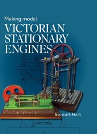
Stationary steam engines provided the power for the Industrial Revolution which changed the shape of the world. Victorian engines that have been preserved now provide the model engineer with examples to turn into fascinating models. This book provides the plans and instructions to make three models of actual steam engines. The projects have been designed around a set of common components. The first project is the simplest and will form the backbone for the manufacture of the other two, which are slightly more challenging and introduce some advanced techniques. The book is suitable for those with limited machining experience and a modestly equipped workshop, and has over 380 illustrations, including scale plans and colour photographs,
Das E-Book können Sie in Legimi-Apps oder einer beliebigen App lesen, die das folgende Format unterstützen:
Seitenzahl: 186
Veröffentlichungsjahr: 2022
Ähnliche


First published in 2022 by
The Crowood Press Ltd
Ramsbury, Marlborough
Wiltshire SN8 2HR
www.crowood.com
This e-book first published in 2022
© Stewart Hart 2022
All rights reserved. This e-book is copyright material and must not be copied, reproduced, transferred, distributed, leased, licensed or publicly performed or used in any way except as specifically permitted in writing by the publishers, as allowed under the terms and conditions under which it was purchased or as strictly permitted by applicable copyright law. Any unauthorised distribution or use of this text may be a direct infringement of the author’s and publisher’s rights, and those responsible may be liable in law accordingly.
British Library Cataloguing-in-Publication Data
A catalogue record for this book is available from the British Library.
ISBN 978 0 7198 4121 7
Cover design by Blue Sunflower Creative
Disclaimer
Safety is of the utmost importance in every aspect of metalworking. When using tools, always follow closely the manufacturer’s recommended procedures. However, the author and publisher cannot accept responsibility for any accident or injury caused by following the advice given in this book.
Dedication
I dedicate this book to my family.
CONTENTS
CHAPTER 1 INTRODUCTION
CHAPTER 2 THE STATIONARY STEAM ENGINE
CHAPTER 3 A BASIC WORKSHOP
CHAPTER 4 OPEN FRAME HORIZONTAL MILL ENGINE COMPONENT MANUFACTURE
CHAPTER 5 VERTICAL CROSS SINGLE COMPONENT MANUFACTURE
CHAPTER 6 SOLDERING
CHAPTER 7 GRASSHOPPER ENGINE COMPONENT MANUFACTURE
CHAPTER 8 YOUR NEXT CHALLENGE IS?
ACKNOWLEDGEMENTS
APPENDIX: STATIONARY STEAM ENGINES ON EXHIBITION
SUPPLIERS TO THE MODEL ENGINEERING HOBBYIST
INDEX
1
Introduction
MANY PEOPLE FROM A non-engineering background are attracted to the fascinating hobby of model engineering. These newcomers struggle at first with how to get started, and I know from experience that they can be overcome with self-doubt when they visit one of the many model engineering exhibitions and see some of the breathtaking models on display. They must put this self-doubt to one side and realize that even these expert builders were once newcomers and, like all model engineers, will have a scrap box. It is possible to build some wonderful models even with the most basic of equipment. To set up a workshop you don’t need a huge amount of space; my own workshop has a floor area of just 3m2 and I know of workshops that are even smaller than this. You just need a small shed, or the corner of a garage (or if you’re really lucky a small spare room) and plenty of imagination on how to best utilize the space you have.
Trilogy of engines, left to right: vertical cross single, Grasshopper haulage engine, open frame horizontal engine.
Some of the basics you will need are a bench with a metal working vice, a small lathe, a pillar drill and a bench top grinder for sharpening tools. In addition, you will need a range of hand tools, files, hammers, etc. The assumption will be that you’re familiar with the machining principles and the basics of these tools.
I am of an age and from a background where I was taught the rudiments of engineering at secondary school: schooling now, particularly in the UK, seems to bypass practical subjects with the emphasis being on more academic studies. So, before anyone embarks on setting up a workshop and taking up the model engineering hobby, I would strongly recommend enrolling in a short course that will teach them the basics. Failing this, join your local model engineering society and get involved in the club activities. If you show sufficient interest, club members will take you under their wing and adopt you as an apprentice. Read as much as you can on the subject: The Crowood Press has some excellent Metalworking Titles, and there are also some very good magazines available.
Taking the first step with a new hobby is always the most difficult. You’ll find yourself inundated with well-meaning advice as to what to undertake for your first project. My advice would be to start off modestly: don’t be too ambitious by jumping in and starting a 5” gauge model of the Flying Scotsman. I can guarantee that it will end up abandoned, hidden away under the bench. Start with something simple that doesn’t require an expensive set of castings and look for something that can be made from low-cost bar stock material. This philosophy has influenced the designs of the three engines covered in this book.
Before you embark on building a model, it helps to have an understanding of how a steam engine works. We will start with a little of the history of stationary steam engines, a basic description of how a steam engine works and the different types of engines. The reader will then be guided through the selection and purchase of a range of basic workshop machinery and tooling, followed by a step-by-step guide to the manufacture of three common types of steam engine.
The first engine is a very basic open frame horizontal mill engine. These types of engine were put to use in a wide range of applications. They were simple to produce and maintain and make an excellent beginner’s engine and will introduce the builder to the manufacture of many of the basic engine parts.
Open frame horizontal engine.
Once some of the basic processes have been perfected, the builder will be able to move onto the modelling of a slightly more challenging project – a vertical cross beam winding engine – specifically of a type that was extensively used in the northeast of England coal fields. This engine will use a lot of parts common to the horizontal engine again using bar stock material.
Vertical cross single.
The final engine in the series is an early example of a Grasshopper haulage engine. These engines were used extensively for hauling minerals and goods up inclines and were the forerunner of the locomotive. Again, the engine uses a lot of parts common to the first two engines but is slightly more challenging, introducing the reader to more advanced techniques. However, for those who don’t want to take on the challenge of these techniques, simpler alternative designs are provided.
Grasshopper haulage engine.
I designed and built these engines a number of years ago, and they were the subject of build articles in the Model Engineer magazine. Since their publication, I know that many examples of the engines have been built so they are well proven and practical designs, suited to the capabilities of a novice builder.
The Stationary Steam Engine
2
THE VICTORIAN STATIONARY STEAM engine powered the industrial revolution that changed the world. It evolved into many types and sizes of engines, providing a fascinating range of projects for the model engineer. Stationary steam engines evolved from the simple condensing engine into many different types of high-pressure engines that had a wide range of applications.
The development of the stationary engine can be traced back to the ground-breaking atmospheric engines of Thomas Newcomen’s first practical fuel driven engines developed around 1712. These engines used the condensing of steam within the cylinder to create a vacuum that sucked the piston down, rocking a beam that was attached to a chain that was in turn attached to a large pump rod that activated a pump at the bottom of the mine shaft, and so drew water from a mine. These engines were gradually refined throughout the 1700s due to improvements in iron casting techniques pioneered by the Coalbrookedale Company. This allowed the manufacture of much larger cylinders, along with minor changes and refinements to the mechanics of the engines.
Newcomen atmospheric pumping engine.
These early engines were very inefficient, with huge amounts of heat energy lost. This was not a problem for engines used to pump water from coal mines that had a ready supply of cheap coal. But it was a problem to the tin and copper mines in Cornwall where the coal had to be expensively shipped from the South Wales coal fields. This led to the invention of the separate condenser by James Watt that, together with further design and manufacturing improvements, increased the efficiency and the power of the engines.
Hundreds of these Newcomen and Watt improved engines had been built by the 1800s, and were employed in mines and iron works where their irregular motion was not a problem. Weaving and spinning sheds, however, required a steady, smooth motion that was being met by waterpower but as demand on the industry increased, sources of suitable waterpower became scarcer.
Watt improved engine with separate condenser.
This demand for power led to further developments of the steam engine with the introduction of double-acting engines where the steam acts on both sides of the piston and the rotative flywheel, thereby smoothing out the motion of the engine. At the same time, improvements in boiler technology led to higher pressures. The Victorians called these higher steam pressures of 40-50 PSI (270-345 kPa) ‘strong steam’. To the modern eye, these pressures are extremely low, but nevertheless these advances led to smaller, more powerful, less expensive and faster engines. These non-condensing engines, driven by the expansive power of steam and coupled to the Watt centrifugal governor, started to meet the power needs of the weaving and spinning sheds. Freed from the geographical constraints of waterpower, cotton towns began to spring up in and around the coal fields of Northern England, where the damp climate was particularly suitable for the spinning and weaving of cotton.
This expansion led to the development of other industries to meet the needs of these textile industries, that in turn drove a rapid expansion of other manufacturing industries. All of which needed a source of cheap, reliable power that was met by the stationary steam engine.
TYPES OF STATIONARY STEAM ENGINES
Beam Engines
The early stationary engines were a development of the Newcomen and Watt pumping engines with several subtle changes. Because they were rotative engines, it wasn’t practical to connect the beam to the piston with a chain, so a fixed coupling was required. The problem here was that the end of the beam moved in an arc which had the effect of pulling the piston rod off centre, resulting in a high-wear rate of the cylinder, piston and piston rod. This led to the invention of a number of ingenious solutions.
Author’s model of a watt parallel motion beam engine.
Watt Parallel Motion
The Watt parallel motion is based on a parallelogram – a four-sided plane where opposite sides are parallel. One of these sides is part of the beam, with one end of the opposite side connected to the piston rod and the other connected via a link to an anchor point, often the wall of the engine house. This arrangement results in a linkage that compensates for the non-linear movement of the end of the beam. Watt parallel motion found use on medium to large engines, many of which were used in the pumping role in mines, water and sewage works.
Beam engine with watt parallel motion.
Grasshopper or Half Beam Engine
The Grasshopper engine was so called because the action of the linkage resembled the leg action of a jumping grasshopper. Another name for this type of engine is the half beam engine. In this type of engine, the connecting rod crank and flywheel is in the middle of the beam. The front of the horizontal beam is connected to the end of the connecting rod with the other end of the beam connected to a vertical rocking beam. The horizontal beam is connected at its midpoint to a link, and the other end of this link connected to an anchor point either to the wall of the engine house or to the entabulator on the end of the cylinder.
Grasshopper or half beam engine.
VERTICAL ENGINES
Hammer Frame Engine
The hammer frame engine is so called because the bedplate and main frame resemble a drop hammer frame. The cylinder can be mounted on the top or bottom of the frame, with the cross head operating on slides. These types of engines were extensively used as marine engines because of their compact design.
Hammer frame vertical engine.
Steeple or Table Engines
The steeple engine was an early attempt for a lighter more compact engine than the beam engine. It consists of a cylinder mounted on top of an entabulator with slide bars mounted on top of the cylinder. Sometimes these slide bars were triangular, hence the name ‘steeple’ engine. The cross head working in these slide bars had connecting rods on either side driving the flywheel. It was found that these engines were too top heavy for use as marine engines, so were used on inland waterways and lakes and for powering workshops.
Steeple or table engine.
Vertical Cross Single
This type of engine was extensively used as a winding engine in the coal fields of the Northeast of England. The flywheel mounted on the top of the engine was also used as the winding drum. A central link is mounted on the pivot point of the piston and crank shaft, and connected at each end are two other links that are anchored to either the walls of the engine house or to supporting pillars.
Vertical cross single engine.
HORIZONTAL ENGINES
Open Frame Horizontal Engine
The simple design of this engine resulted in thousands (both big and small) being made by a wide range of local manufactures. They were used in various applications: driving workshops, spinning and weaving mills, breweries, flint mills, etc. They could be made small enough to take on a portable roll, driving threshing machines, sawmills and fairground rides. They were truly a universal source of power. They consisted of a bedplate with a cylinder bolted on the top with two pairs of slide bars that the cross head worked in, that was then connected to the connecting rod that drove the crank shaft and flywheel.
Horizontal open frame engine.
Self-contained Horizontal Engine
These are like the open frame engine but were built on a more complicated cast bedplate that had the slides as an integral part of the bedplate with the cylinder bolted onto the end of the casting. This arrangement complicated the bedplate manufacture.
Self-contained horizontal engine.
These are just a few of the more common types of successful engine types: but many more different types of engines were designed, some of which never got off the drawing board; others never got past the prototype stage or were financial failures. However, this doesn’t mean that they aren’t suitable for a model engineering project – their eccentricity just adds to the challenge and fascination for the modeller.
Author’s model of a Simpson and Shipton engine that was a technical and financial failure.
COMPOUND ENGINES
With a single cylinder, ‘simple’ engine, high pressure steam from the boiler is fed into the cylinder that forces the piston forwards. At around a ¼ of this forwards movement, the valve shuts off to ‘cut off’, and the trapped steam expands for the remaining travel of the piston. The early cut off of the valve allows more work to be extracted from the steam. As the steam expands, its temperature reduces and with each stroke the temperature increases and decreases which is a source of inefficiency. To lessen this heating and cooling effect, the compound engine was invented by Arthur Woolf in 1804 who patented the ‘Wolf high pressure compound engine’.
Compound engine steam flow.
In a compound engine, high pressure steam enters the high-pressure cylinder from the boiler. The used steam is exhausted into a low-pressure cylinder which can exhaust into a third or even a fourth cylinder. Each cylinder uses the steam to produce power, This gradual expansion of the steam results in less heat loss. The volume of each cylinder increases to compensate for the pressure drop so each cylinder produces equal amount of work. This results in increased efficiency and power, smoother running and lighter engines with a higher power to weight ratio. These engines found great use in the marine environment.
Many early beam engines were converted to compounds by adding additional cylinders. Sometimes the cylinder was added at the same end of the beam as the existing cylinders, and on others they were added at the opposite end. These types were known as McNaught compound beam engines after the engineer who pioneered this modification.
COMMON ENGINE PARTS
For a reader not from an engineering background, a brief explanation of the names and functions of some of the main parts that are common to most stationary engines would be helpful. The names of different engine parts are not always universally used – there are some regional and industry variations, so to the uninitiated this can be baffling. Throughout the text I’ve kept to the same names, or I’ve used the names I think best describes the part so that they are obvious to the reader.
Bedplate: The bedplate forms the foundation of the engine onto which other parts are attached. It is usually a large casting, but in some cases the actual floor of the engine house serves as the bedplate.
Cylinder: The cylinder is the heart of the engine. Integral parts of the cylinder are steam passageway and fixing points for the valve chest, end covers and other ancillary parts.
Piston: The piston is fitted with a seal and is a close fit in the cylinder. Steam pressure acts on the faces of the piston moving it in the cylinder. In a single-acting cylinder, the pressure acts on just one face powering just one stroke of the engine. In a double-acting engine, the pressure acts on each face of the cylinder in turn, powering the forward and return stroke of the engine.
Rear and front covers: These close and make the cylinder steam tight with the front cover, forming a stuffing box cavity to take a seal that wraps round the piston rod making it steam tight.
Piston rod guide: This forms a guide for the piston rod and compresses the sealing material in the stuffing box to forming a seal around the piston rod.
Connection rod: This connects the crank shaft to the end of the piston rod via a cross head assembly.
Cross head assembly: This is a swiveling joint that joins the piston rod to the connecting rod. It works in a slide, or is connected to some other form of linkage, so that the piston rod moves in a straight line.
Slide bar assembly: The slide bar assembly acts as a guide to the cross head ensuring that the piston rod moves in a straight line.
Valve chest: The valve chest encloses the valve mechanism, bolting onto the side of the cylinder.
Valve: The valve can be a slide valve, piston valve or rotary valve. It moves backwards and forwards opening or closing ports to allow the flow of steam into the cylinder or exhaust of steam out of the cylinder.
Valve rod: The valve rod connects the valve to the linkage that connects to eccentric rod.
Eccentric rod: This connects the valve linkage to the eccentric.
Eccentric assembly: The eccentric generates the backwards and forwards motion of the valve. It consists of two parts: the eccentric itself (that has an offset hole that fastens to the crank shaft) and the eccentric sleeve that runs in a groove formed in the eccentric. The sleeve connects to the rod that operates the valve.
Crank shaft: The crank shaft changes the forwards and backwards (linear) motion of the piston to rotary motion. The eccentric, flywheel and power take offs are all connected to it.
Bearing stand assembly: The bearing stand bolts to the bedplate and holds the bearing in which the crank shaft runs.
Flywheel: The flywheel is basically an energy store. It smooths out small deviations in the power output and so stabilizes the revolutions per minute and power output.
Common engine parts.
CYLINDER AND CRANK CONFIGURATION
There are many different ways to configure cylinders and cranks that depend on the constraints and power output duties demanded of the engine.
Common cylinder and crank shaft configuration.
TYPES OF VALVE
The various methods of feeding steam into the cylinder of an engine all are activated by an eccentric on the crank shaft. The three main types are as follows:
Types of valve layout.
Slide Valve
Steam is fed into the valve chest and around the outside of the slide valve. The steam pressure helps to seal the face of the valve onto the face of the cylinder. This is called ‘outside steam admission’. With outside steam admission, the eccentric follows the crank shaft by 90°. The eccentric moves the slide valve backwards and forwards in the valve chest. The flat face of the slide valve has a recess cut into it and the top of the valve has an adjustable connection to the valve rod. The flat face of the cylinder has three slots or ports cut into it. The two outer ports are connected via steam galleries to the front of the cylinder. The slide valve opens these ports in turn, allowing the steam to activate the piston. The middle or exhaust port is linked to one of the two outer ports via the slide valve recess allowing the steam to exhaust via the recess.
Piston Valve
This valve consists of a bobbin-shaped piston that slides in the steam chest. The steam chest has a central steam inlet and two exhaust ports at either end. The cylinder has two inlet ports and galleries similar to the those for a slide valve. When the valve is in the forwards position, steam flows through the centre of the valve feeding steam to the front of the piston. The exhaust steam flows around the outside of the valve. When the eccentric moves the valve to the rear position, steam is fed to the rear of the piston. This arrangement is called ‘inside steam admission’. With inside admission, the eccentric leads the crank shaft by 90°.
Corliss Rotary Valve
The Corliss valve consist of four rotary valves – two at the top and two at the bottom of the cylinder. These are activated via links connected to a rotary wrist plate that is connected to the valve rod and is activated via the eccentric. The system incorporates trips and mechanisms that controls the timing of the opening and closing of the valves, resulting in a very thermal efficient steam engine.
Corliss valve horizontal mill engine.
VALVE GEOMETRY


