171,99 €
Mehr erfahren.
- Herausgeber: John Wiley & Sons
- Kategorie: Fachliteratur
- Sprache: Englisch
When installed and operated properly, general purpose steam turbines are reliable and tend to be forgotten, i.e., out of sound and out of mind. But, they can be sleeping giants that can result in major headaches if ignored. Three real steam turbine undesirable consequences that immediately come to mind are: * Injury and secondary damage due to an overspeed failure. An overspeed failure on a big steam or gas turbine is one of the most frightening of industrial accidents. * The high cost of an extensive overhaul due to an undetected component failure. A major steam turbine repair can cost ten or more times that of a garden variety centrifugal pump repair. * Costly production loses due an extended outage if the driven pump or compressor train is unspared. The value of lost production can quickly exceed repair costs. A major goal of this book is to provide readers with detailed operating procedure aimed at reducing these risks to minimal levels. Start-ups are complicated by the fact that operators must deal with numerous start-up scenarios, such as: * Commissioning a newly installed steam turbine * Starting ups after a major steam turbine repair * Starting up a proven steam turbine after an outage * Overspeed trip testing It is not enough to simply have a set of procedures in the control room for reference. To be effective, operating procedures must be clearly written down, taught, and practiced--until they become habit.
Sie lesen das E-Book in den Legimi-Apps auf:
Seitenzahl: 266
Veröffentlichungsjahr: 2016
Ähnliche


Contents
Cover
Title page
Copyright page
Dedication
Preface
Acknowledgements
Chapter 1: Introduction to Steam Turbines
1.1 Why Do We Use Steam Turbines?
1.2 How Steam Turbines Work
1.3 Properties of Steam
1.4 Steam and Water Requirements
Questions
Answers
Chapter 2: General Purpose Back Pressure Steam Turbine
2.1 Single-Stage Back Pressure Steam Turbine
2.2 Mechanical Components in General Purpose Back Pressure Steam Turbines
Questions
Answers
Chapter 3: Routine Steam Turbine Inspections
Questions
Answers
Chapter 4: Steam Turbine Speed Controls and Safety Systems
4.1 Introduction
4.2 Speed Controls
4.3 Governor Classes
4.4 Overspeed Trip System
4.5 Overpressure Protection
4.6 Additional Advice
Questions
Answers
Chapter 5: The Importance of Operating Procedures
5.1 Steam Turbine Start-up Risks
5.2 Starting Centrifugal Pumps and Compressors
5.3 Steam Turbine Train Procedures
5.4 Training Options
Questions
Answers
Chapter 6: Overspeed Trip Testing
6.1 Overspeed Trip Pre-test Checks
6.2
Uncoupled
Overspeed Trip Test Procedure
6.3 Acceptance Criteria for Overspeed Trip Test
Questions
Answers
Chapter 7: Centrifugal Pump and Centrifugal Compressor Start-ups with a Steam Turbine Driver
7.1 Centrifugal Pump and Steam Turbine Start-up
7.2 Centrifugal Compressor and Steam Turbine Start-up
Questions
Answers
Chapter 8: Centrifugal Pump and Centrifugal Compressor Shutdowns with a Steam Turbine Driver
8.1 Centrifugal Pump Steam Turbine Shutdown
8.2 Centrifugal Compressor Steam Turbine Shutdown
Questions
Answers
Chapter 9: Installation, Commissioning and First Solo Run
9.1 Introduction
9.2 Equipment Installation
9.3 Commissioning
9.4 Turbine First Solo Run on Site
Questions
Answers
Chapter 10: Reinstating Steam Turbine after Maintenance
10.1 Turbine Reinstatment after Maintenance
10.2 Reinstatement after Maintenance Check List
10.3 Steam Turbine Reinstatement after Maintenance Procedure (Refer to Figure 10.1)
Questions
Answers
Chapter 11: Steam Turbine Reliability
11.1 Repairs versus Overhauls
11.2 Expected Lifetimes of Steam Turbines and Their Components
11.3 Common Failure Modes
11.4 Improvement Reliability by Design
Questions
Answers
Chapter 12: Introduction to Field Troubleshooting
12.1 Common Symptoms
12.2 Common Potential Causes
12.3 Troubleshooting Example #1
12.4 Troubleshooting Example #2
12.5 Steam Turbine Troubleshooting Table
12.6 Other Troubleshooting Approaches
Questions
Answers
Chapter 13: Steam Turbine Monitoring Advice
13.1 What Is the Steam Turbine Speed Telling You?
13.2 Assessing Steam Turbine Vibrations
13.3 Steam Turbine Temperature Assessments
13.4 Common Governor Control Problems
13.5 Other Inspections
13.6 Good Rules of Thumb for Steam Turbines
Questions
Answers
Chapter 14: Beyond Start-ups, Shutdowns, and Inspections
Appendix A: An Introduction to Steam Turbine Selection
Appendix B: Glossary of Steam Turbine Terms
Appendix C: Predictive Maintenance Activity with Recommended Intervals
Appendix D: Properties of Saturated Steam
Index
End User License Agreement
Guide
Cover
Copyright
Contents
Begin Reading
List of Tables
Chapter 1
Table 1.1 Properties of saturated steam.
Chapter 4
Table 4.1 The table lists governor specifications as percentages of maximum continuous speed. he maximum continuous speed is defined as the highest speed at which the turbine, as built and tested, is capable of continuous operation, at any of the specified steam conditions.
Table 4.2 Trip settings as a percentage of maximum continuous speed.
Chapter 6
Table 6.1 Overspeed trip speed tolerances.
Table 6.2 Example data from an overspeed trip test.
Chapter 9
Table 9.1 Wire mesh dimensional information.
Chapter 11
Table 11.1 Expected lifetimes of process machines and components.
Table 11.2 Mean time between repairs (in yrs.) for various design configurations.
Chapter 12
Table 12.1 Possible cause for “Steam turbine does not achieve rated power”.
Table 12.2 Common symptoms and their possible causes.
Chapter 13
Table 13.1 ISO evaluation standard.
Table 13.2 Steam turbine vibration analysis basics.
Appendix A
Table A.1
Section of superheated steam table.
Table A.2
Section of saturated steam table.
Table A.3
Common Steam Turbine shaft material.
List of Illustrations
Chapter 1
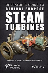
Figure 1.1 General purpose steam turbine. (Courtesy of Elliott Group)
Figure 1.2 Basic impulse steam turbine.
Figure 1.3 Cross section of an impulse steam turbine.
Figure 1.4 Waste heat boiler.
Figure 1.5 Steam drum.
Figure 1.6 Components of a boiler/steam turbine system.
Figure 1.7 Tea kettle producing steam.
Figure 1.8 Condensing steam turbine (on the left) and non-condensing steam turbine (on the right). Notice that the non-condensing steam turbine exhausts into an intermediate pressure steam header.
Figure 1.9 Extraction type steam turbine.
Figure 1.10 General purpose steam turbine. (Courtesy of Elliott Group)
Chapter 2
Figure 2.1 General purpose back pressure steam turbine. (Courtesy of Elliott Group)
Figure 2.2 Inlet screen to steam turbine upstream of the trip valve. (Courtesy of Elliott Group)
Figure 2.3 View of the trip valve and governor valve. (Courtesy of Elliott Group)
Figure 2.4 Single-stage steam turbine cross section. (Courtesy of Elliott Group) Arrows indicate steam flow.
Figure 2.5 View of nozzle ring which is typically bolted to the inside of the steam turbine upstream of the rotating blades. (Courtesy of Elliott Group)
Figure 2.6 Complete nozzle ring. (Courtesy of Elliott Group)
Figure 2.7 Comparison of impulse-type and reaction-type steam turbines.
Figure 2.8 The purpose the non-moving blades or fixed blades serve is to redirect steam from the first set of moving blades on to the second set of moving blades.
Figure 2.9 Rotating blades attached to a solid disk.
Figure 2.10 Notice the large exhaust flange exit on the lower left portion of this photo. (Courtesy of Elliott Group)
Figure 2.11 Hand valves allow users to control the amount of steam flow supplied to the stationary and rotating blades.
Figure 2.12 A hydrodynamic or sleeve bearing works by developing an oil wedge that gets trapped between the bearing and the rotating shaft. The oil wedge generates sufficient pressure to raise the shaft up off the bearing surface.
Figure 2.13 Typical ball bearing designs.
Figure 2.14 Oil ring lubrication showing rings contacting oil sump. Also notice the constant level oiler connected to the oil sump or reservoir.
Figure 2.15 Location of lube oil rings on top of bearing; bronze or brass material typically. (Courtesy of Elliott Group)
Figure 2.16 Oil rings used for oil ring lubrication.
Figure 2.17 View of constant level oiler with ball bearings contacting oil in sump.
Figure 2.18 Basic forced lubrication system. Pump, bearings and oil reservoir.
Figure 2.19 Complex forced lubrication system with pumps, reservoir in blue, coolers, extraction fans on top of reservoir.
Figure 2.20 Side view of lip seal with garter spring.
Figure 2.21 Shaft is rotating and labyrinth teeth are stationary in the bearing housing.
Figure 2.22 Labyrinth teeth mounted on the shaft provide an additional barrier to oil seal leakage due to centrifugal force.
Figure 2.23 Bearing Isolators provide the most effective oil seals for bearing housings. (Courtesy of Inpro/Seal LLC)
Figure 2.24 Labyrinth seal mounted on the housing sealing on the shaft. (Courtesy of Elliott Group)
Figure 2.25 Three segmented carbon rings with garter or retainer spring and anti-rotation pin.
Figure 2.26 Steam steals or Packing. Notice the carbon seals and housing. (Courtesy of Elliott Group)
Figure 2.27 Carbon packing gland.
Figure 2.28 Overview of the general purpose steam turbine. Notice the location of the ball bearings, carbon seals, oil rings, rotating and stationary blades, shaft connection to governor, and oil housing seals. (Courtesy of Elliott Group)
Chapter 3
Figure 3.1 Look, listen, and feel.
Figure 3.2 Condensate or free water in a steam turbine’s inlet will lead to the rapid erosion of the steam path components, which is why steam traps are always installed in steam turbine inlet piping. A steam trap is used to remove condensate and non-condensable gases from steam piping, with a negligible consumption or loss of live steam.
Chapter 4
Figure 4.1 Basic mechanical governor.
Figure 4.2 Mechanical-Hydraulic governor details.
Figure 4.3 Woodward mechanical-hydraulic governor. One of the most common types of turbine governors (TG) used to control general purpose steam turbines. (Courtesy of Woodward Inc.)
Figure 4.4 The overall governor system and its linkage from the mechanical-hydraulic governor. It should be noted that the governor controls only the governor valve or throttle valve. This is the only valve that controls the steam going into the turbine.
Figure 4.5 Magnetic speed sensor used in electronic governors. Each pass of the gear tooth produces a pulse in the sensor winding.
Figure 4.6 Double-seated trip valve. (Courtesy Elliott Group)
Figure 4.7 Spring-loaded pin or weight. 1. Body, 2. Pin, 3. Spring, 4. Lock U-Staple, 5. Adjustable nut, 6. Washer, 7. Auxiliary weight.
Figure 4.8 Typical mechanical-hydraulic governor arrangement. Notice linkage connection between governor valve and governor. (Courtesy of Elliott Group)
Figure 4.9 Steam turbine with a sentinel valve on top of the exhaust casing. (Courtesy of Elliott Group)
Chapter 5
Figure 5.1 Pothole.
Chapter 6
Figure 6.1 Steam turbine piping schematic.
Chapter 7
Figure 7.1 Typical steam turbine and centrifugal pump train.
Figure 7.2 Typical steam turbine and centrifugal compressor train.
Chapter 8
Figure 8.1 Typical steam turbine and centrifugal pump train.
Figure 8.2 Typical steam turbine and centrifugal compressor train.
Chapter 9
Figure 9.1 General overview of a typical equipment foundation which will support rotating equipment.
Figure 9.2 Notice the installation of the anchor bolt, mounting plate, rebar, chamfered edge for the concrete and grout, protective anchor bolt sleeve and mounting plate.
Figure 9.3 Typical soleplate. Notice that all the corners have a radius (rounded) to reduce stress areas in the grout. The radius corner should be at least 2 inches.
Figure 9.4 Typical grouting installation of soleplate.
Figure 9.5 Machinist levels should be used to ensure all baseplate pads are level and flat. Leveling must be done in two directions, lengthwise (with shafts) and crosswise transverse (perpendicular to shafts).
Figure 9.6 Machinist levels should be used to check the baseplate level, flatness and in the same plan in the lengthwise and crosswise directions.
Figure 9.7 Cross sectional view of the foundation with a grouted in sole plate, stainless steel shims and machine base.
Figure 9.8 Typical mounting plate arrangement for baseplate mounted equipment. Notice the use of soleplates supporting the structural baseplate. The entire structural steel baseplate will be grouted in place.
Figure 9.9 Equipment flange to pipe flange alignment requirements.
Figure 9.10 Piping alignment for parallel flanges.
Figure 9.11 One method to check for excessive pipe strain on equipment is with dial indicators while the pipe to equipment flange is being made and bolts torqued.
Figure 9.12 This is a typical bracket support for the polished target and shows the location of the target mounted at the exit of the steam piping. The target should be located in the middle of the steam blowing piping.
Figure 9.13 Typical target configuration, metal strip. The middle section in green is the only area to be viewed for the pass/fail criteria.
Figure 9.14 Examples of raised impact and non-raised impacts.
Figure 9.15 Acceptance criteria for any size cluster in a 1 inch by 1 inch square.
Figure 9.16 The pointed part of the strainer typically points toward the flow.
Figure 9.17 Notice the oil rings, red preservation coating inside the lube oil sump. (Courtesy of Elliott Group)
Figure 9.18 Full governor linkage movement from no-load to full load.
Figure 9.19 Uncoupled steam turbine.
Chapter 10
Figure 10.1 Uncoupled steam turbine.
Chapter 12
Figure 12.1 A fish bone diagram is one of many analysis tools that can be used when troubleshooting steam turbines.
Chapter 13
Figure 13.1 Operators should use their eyes, nose, ears, and sense of touch to monitor the condition of their steam turbines.
Figure 13.2 Typical self-contained mechanical-hydraulic governors used on small steam turbines. (Courtesy of Woodard Inc.)
Figure 13.3 Carbon ring packing seals are shown on the right and labyrinth seal on the left.
Figure 13.4 Varnish Formation on Plain Bearing and Shaft.
Figure 13.5 Broken pipe hanger support.
Appendix A
Figure A.1 Velocity Ratio vs turbine efficiency for single-stage turbine.
Pages
ii
iii
iv
v
xiii
xiv
xv
xvi
xvii
xix
1
2
3
4
5
6
7
8
9
10
11
12
13
14
15
16
17
18
19
20
21
22
23
24
25
26
27
28
29
30
31
32
33
34
35
36
37
38
39
40
41
42
43
44
45
46
47
48
49
50
51
52
53
54
55
56
57
58
59
60
61
62
63
64
65
66
67
68
69
70
71
72
73
74
75
76
77
78
79
80
81
82
83
84
85
86
87
88
89
90
91
92
93
94
95
96
97
98
99
100
101
102
103
104
105
106
107
108
109
110
111
112
113
114
115
116
117
118
119
120
121
122
123
124
125
126
127
128
129
130
131
132
133
134
135
136
137
138
139
140
141
142
143
144
145
146
147
148
149
150
151
152
153
154
155
156
157
158
159
160
161
162
163
164
165
166
167
168
169
170
171
172
173
174
175
176
177
178
179
180
181
182
183
184
185
186
187
188
189
190
191
192
193
194
195
196
197
198
199
200
201
202
203
204
205
206
207
208
209
210
211
212
213
214
215
216
217
218
219
220
221
222
223
224
225
226
227
228
229
230
231
232
233
234
235
236
237
238
239
240
241
242
243
244
245
246
247
248
249
250
251
252
253
254
255
256
257
258
259
260
261
262
263
264
265
266
267
268
269
270
271
272
273
274
275
276
277
278
279
280
281
282
283
284
285
286
287
288
289
290
291
292
293
294
295
296
297
298
299
300
301
302
303
304
305
306
307
308
309
310
311
312
Scrivener Publishing 100 Cummings Center, Suite 541J Beverly, MA 01915-6106
Publishers at Scrivener Martin Scrivener ([email protected]) Phillip Carmical ([email protected])
Operator’s Guide to General Purpose Steam Turbines
An Overview of Operating Principles, Construction, Best Practices, and Troubleshooting
Robert X. Perez and David W. Lawhon
Copyright © 2016 by Scrivener Publishing LLC. All rights reserved.
Co-published by John Wiley & Sons, Inc. Hoboken, New Jersey, and Scrivener Publishing LLC, Salem, Massachusetts. Published simultaneously in Canada.
No part of this publication may be reproduced, stored in a retrieval system, or transmitted in any form or by any means, electronic, mechanical, photocopying, recording, scanning, or otherwise, except as permitted under Section 107 or 108 of the 1976 United States Copyright Act, without either the prior written permission of the Publisher, or authorization through payment of the appropriate per-copy fee to the Copyright Clearance Center, Inc., 222 Rosewood Drive, Danvers, MA 01923, (978) 750-8400, fax (978) 750-4470, or on the web at www.copyright.com. Requests to the Publisher for permission should be addressed to the Permissions Department, John Wiley & Sons, Inc., 111 River Street, Hoboken, NJ 07030, (201) 748-6011, fax (201) 748-6008, or online at http://www.wiley.com/go/permission.
Limit of Liability/Disclaimer of Warranty: While the publisher and author have used their best efforts in preparing this book, they make no representations or warranties with respect to the accuracy or completeness of the contents of this book and specifically disclaim any implied warranties of merchantability or fitness for a particular purpose. No warranty may be created or extended by sales representatives or written sales materials. The advice and strategies contained herein may not be suitable for your situation. You should consult with a professional where appropriate. Neither the publisher nor author shall be liable for any loss of profit or any other commercial damages, including but not limited to special, incidental, consequential, or other damages.
For general information on our other products and services or for technical support, please contact our Customer Care Department within the United States at (800) 762-2974, outside the United States at (317) 572-3993 or fax (317) 572-4002.
Wiley also publishes its books in a variety of electronic formats. Some content that appears in print may not be available in electronic formats. For more information about Wiley products, visit our web site at www.wiley.com.
For more information about Scrivener products please visit www.scrivenerpublishing.com.
Library of Congress Cataloging-in-Publication Data:
ISBN 978-1-119-29421-4
We dedicate this book to our families for their constant support and encouragement.
Preface
“We are what we repeatedly do. Excellence, then, is not an act, but a habit.”
—Aristotle
If you operate steam turbines in your plant you are probably asking: Why do I need a whole book devoted to steam turbine operations? The short answer is because we all want our steam turbines to operate reliably and safely during their lifetimes and to avoid nasty surprises, such as massive failures, unexpected outages or injuries. Owners of steam turbines should continuously strive to protect life, limb and property and minimize the life cycle costs through the use of proven operating practices like those contained in this book. The best practices presented in this book can be used as a basis for your plant’s steam turbine reliability program and operating procedures.
The life cycle cost (LCC) of a machine is the total of the purchase, installation, repair, and operating costs incurred throughout its lifetime. As an operator the only way to affect a steam turbine LCC is by minimizing maintenance cost. This is accomplished by employing proven start-up procedures that will minimize undue stresses and erosion and by monitoring them in order to detect minor issues before they lead to costly repairs. General purpose (GP) steam turbine drivers present operators with special challenges because they tend to have a minimum of automation and instrumentation which makes their reliability dependent on the skill and knowledge of their caretakers. In other words, their reliability is dependent on the quality of human implemented procedures and human-based monitoring methods.
When installed and operated properly, GP steam turbines are reliable and tend to be forgotten, “out of sight, out of mind”. But these sleeping giants can create major headaches if ignored. Three real steam turbine undesirable consequences that immediately come to mind are:
Injury and secondary damage due to an overspeed failure.
An overspeed failure on a large steam or gas turbine is one of the most frightening of industrial accidents. A huge amount of thermal, chemical, and mechanical energy is contained within a large steam turbine when it is in service. If the rotational speed of the steam turbine ever exceeds its safe operating limits, the main shaft and impeller wheels can be pulled apart by centrifugal force, releasing a tremendous amount of energy. In the worst case, the disintegrating parts can break through the turbine housing and fling hot, fast-moving shards of metal in all directions. The results of such a failure are always very costly due to the peripheral equipment damage and can sometimes be fatal to personnel in the area.
The high cost of an extensive overhaul due to an undetected component failure.
The cost of a major steam turbine repair can run ten or more times that of a garden variety centrifugal pump repair. If an early failure is not detected, it will usually result in a more costly failure. For example, a simple packing leak can result in oil contamination, which can lead to a bearing failure, which can lead to major rotor damage. Repair cost can rapidly escalate if the chain of failure events is not stopped early, i.e., in the primary stage.
Costly production losses due an extended outage if the driven pump or compressor train is unspared.
The value of lost production can quickly exceed repair costs. Extending the mean time between repairs though the implementation of best practices will in turn reduce production downtime and dramatically increase overall profits.
A major goal of this book is to provide readers with detailed operating procedure aimed at reducing these risks to minimal levels. Start-ups are complicated by the fact that operators must deal with numerous scenarios, such as:
Overspeed trip testing
Starting up a proven steam turbine driver after an outage
Shutting down a steam turbine driving a centrifugal pump or centrifugal compressor
Commissioning a newly installed steam turbine
Starting up after a major steam turbine repair
It is not enough to simply have a set of procedures in the control room for reference. To be effective, operating procedures must be clearly written down, taught, and practiced—until they become habit. Operators must be fully committed to following the prescribed steam turbine operating procedure every time and carefully monitoring them in the field in order to detect signs of early failures before serious damage is done. To support this commitment this book will:
Provide operators with a broad exposure to the principles of steam turbine design and operations
Explain common failure modes and how they can be prevented or mitigated and
Provide proven operating procedures that can protect your steam turbines from costly and dangerous failures.
The authors hope the reader will find the contents of this book to be useful and applicable in their present assignment. We also hope the ideas and suggestions provided here compel you to commit yourself to operational excellence.
Robert X. Perez and David W. Lawhon
Acknowledgements
The authors thank the following individuals who helped in various aspects of the book development:
Ron Reeves for providing steam turbine reliability data
Julien LeBleu for providing steam turbine inspection guidelines
Danny Lawhon for providing an operator’s perspective on turbine procedures
Elaine Perez and Carolyn Dulak for proofreading and editing the manuscript
Tom Brown and David Pribish with Elliott Group, Jeanne Lasley with Woodward Inc., and Jason Putnam with Inpro/Seal LLC for expediting the approval of photos and drawings
Chapter 1Introduction to Steam Turbines
1.1 Why Do We Use Steam Turbines?
Steam turbine drivers are prime movers that convert the thermal energy present in steam into mechanical energy through the rotation of a shaft. Industrial steam turbines fit into one of two general categories: generator drives and mechanical drives. Generator drives include all turbines driving either synchronous or induction generators for power generation. In this book, we will cover primarily steam turbines used in the petrochemical industry as mechanical drives for centrifugal pumps and centrifugal compressors. In mechanical drives, the rotational energy is transmitted to a process machine that in turn converts it into fluid energy required to provide flow for a given process.
Heat energy → Steam energy → Rotational energy → Fluid energy
Figure 1.1 General purpose steam turbine. (Courtesy of Elliott Group)
1.2 How Steam Turbines Work
Steam turbines are relatively simple machines that use high-velocity steam jets to drive a bladed wheel that is attached to a rotating shaft. Figure 1.2 depicts an impulse-type steam turbine in its most basic form: A steam nozzle and a bucketed, rotating wheel.
Figure 1.2 Basic impulse steam turbine.
In this design, high-pressure steam is accelerated to a high velocity in the stationary nozzle and then directed onto a set of blades or buckets attached to a wheel. As the steam jet impacts the buckets, it is deflected and then leaves the scene. The change in momentum involved in the steam’s deflection generates a force that turns the wheel in the direction opposite of the incoming steam jet. If the wheel is affixed to a shaft and supported by a set of bearings, rotational power can be transmitted via the output shaft.
To produce useful work in a safe and reliable manner, an impulse-type steam turbine, at a minimum, must contain:
A bladed wheel that is attached to a shaft.
A set of stationary steam nozzles capable of accelerating high-pressure steam to create high velocity jets. (See the steam nozzle in
Figure 1.3
.)
A pressure-containing casing.
Seals that can control steam leakage from traveling down the shaft. (See carbon packing end seals in
Figure 1.3
.)
A governor system capable of controlling rotating speed within design specifications. (Speed governor in
Figure 1.3
.) Governor systems fall into two main categories: hydraulic and electronic.
A coupling that can transmit power from the steam turbine to an adjacent centrifugal machine.
Figure 1.3 Cross section of an impulse steam turbine.
Steam turbines can be rated anywhere from a few horsepower to around a million horsepower. They can be configured to drive generators to produce electricity, or mechanical machines such as fans, compressors, and pumps. Steam turbines can be designed to operate with a vertical or horizontal rotor, but are most often applied with horizontal rotors.
1.2.1 Steam Generation
Steam is either generated in a boiler or in a heat recovery steam generator by transferring the heat from combustion gases into water. When water absorbs enough heat, it changes phase from liquid to steam. In some boilers, a super-heater further increases the energy content of the steam. Under pressure, the steam then flows from the boiler or steam generator and into the distribution system.
1.2.2 Waste Heat Utilization
Waste heat conversion is the process of capturing heat discarded by an existing industrial process and using that heat to generate low-pressure steam. Energy-intensive industrial processes—such as those occurring at refineries, steel mills, glass furnaces, and cement kilns—all release hot exhaust thermal energy in the form of hot liquid streams that can be captured using waste heat boilers (see Figure 1.4).
Figure 1.4 Waste heat boiler.
The steam from waste heat boilers can be utilized for heating purposes or to power steam turbines.
Steam systems all tend to have the following elements:
Boiler—A process subsystem that uses a fired fuel or waste heat to turn condensate into high-pressure steam. Steam is typically collected in a steam drum (see
Figure 1.5
)
Steam Turbine—A rotating machine that converts high-pressure steam energy into shaft power
Process Waste Heat Recovery or Condenser—A part of the process that recovers sufficient lower pressure steam heat to condense all the steam back to condensate
Boiler Feedwater Pump—A liquid pump that raises condensate pressure back to boil pressure so that it can be returned to the steam boiler
Figure 1.5 Steam drum.
1.2.3 The Rankine Cycle
The Rankine cycle is the thermodynamic basis for most industrial steam turbine systems. It consists of a heat source (boiler) that converts water to high-pressure steam. In the steam cycle, water is first pumped up to elevated pressure and sent to a boiler. Once in the boiler, liquid water is then heated to the boiling temperature corresponding to the system pressure until it boils, i.e., transforms from a liquid into water vapor. In most cases, the steam is superheated, meaning it is heated to a temperature above that required for boiling. The pressurized steam is: (a) transmitted via piping to a multistage turbine, where it is (b) expanded to lower pressure and then (c) exhausted either to a condenser at vacuum conditions or into an intermediate temperature steam distribution system. Intermediate pressure steam is often used for other process applications at a nearby site. The condensate from the condenser or from the industrial steam utilization system is returned to the feedwater pump for continuation of the cycle.
Primary components of a boiler/steam turbine system are shown in Figure 1.6.
Figure 1.6 Components of a boiler/steam turbine system.
1.3 Properties of Steam
Water can exist in three forms, ice, liquid and gas. If heat energy is added to water, its temperature will rise until it reaches the point where it can no longer exist as a liquid. We call this temperature the “saturation” point, where with any further addition of heat energy, some of the water will boil off as gaseous water, called steam. This evaporation effect requires relatively large amounts of energy per pound of water to convert the state of water into its gaseous state. As heat continues to be added to saturated water, the water and the steam remain at the same temperature, as long as liquid water is present in the boiler.
The temperature at which water boils, also called boiling point or saturation temperature, increases as the pressure in the vapor space above the water increases. As the water vapor pressure increases above the atmospheric pressure, its saturation temperature rises above 212 °F. The table below titled, “Properties of Saturated Steam” illustrates how the saturated steam temperature increases with increasing steam pressure.
Figure 1.7 Tea kettle producing steam.
If heat is added after the steam has left the boiler, without an increase in steam pressure, superheated steam is produced. The temperature of superheated steam, expressed as degrees above saturation corresponding to the pressure, is referred to as the degrees of superheat. Adding superheat to steam is a good way to prevent steam from condensing as it makes its way from a boiler to a steam turbine.
In general, we can say that the higher the steam pressure and its corresponding temperature the more energy it contains to perform useful work. In order to get a feel for typical saturated steam pressure and temperature, we will provide a few realistic examples. Refer to the “Properties of Saturated Steam” (Table 1.1) as you consider the following examples:
Table 1.1 Properties of saturated steam.
Absolute pressure (psia)
Gauge pressure (psig)
Steam temp. (°F)
With 10 degrees superheat
165
150.30
365.99
375.99
175
160.30
370.75
380.75
195
180.30
379.67
389.67
215
200.30
387.89
397.89
240
225.30
397.37
407.37


