Erhalten Sie Zugang zu diesem und mehr als 300000 Büchern ab EUR 5,99 monatlich.
- Herausgeber: The Crowood Press
- Kategorie: Lebensstil
- Sprache: Englisch
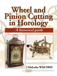
Many clock repairers carry out excellent work but avoid cutting their own wheels and pinions, fearing it is too complicated and involved. This book, written by an experienced clock and tool maker, dispels those fears and gives a step-by-step guide to an extremely satisfying aspect of horology. This book is written for both the amateur and professional involved in the making and restoring of clocks, and for anyone who intends to start building up a workshop and requires a guide to the equipment and how to use it.
Sie lesen das E-Book in den Legimi-Apps auf:
Seitenzahl: 298
Veröffentlichungsjahr: 2001
Das E-Book (TTS) können Sie hören im Abo „Legimi Premium” in Legimi-Apps auf:
Ähnliche


First published in 2001 by
The Crowood Press Ltd
Ramsbury, Marlborough
Wiltshire SN8 2HR
www.crowood.com
This impression 2021
This e-book first published in 2024
© J Malcolm Wild 2001
All rights reserved. This e-book is copyright material and must not be copied, reproduced, transferred, distributed, leased, licensed or publicly performed or used in any way except as specifically permitted in writing by the publishers, as allowed under the terms and conditions under which it was purchased or as strictly permitted by applicable copyright law. Any unauthorised distribution or use of this text may be a direct infringement of the author’s and publisher’s rights, and those responsible may be liable in law accordingly.
British Library Cataloguing-in-Publication Data
A catalogue record for this book is available from the British Library.
ISBN 978 0 7198 4361 7
Photography and line illustrations by the author
CONTENTS
PREFACE
1 EARLY METHODS OF CUTTING WHEELS
2 PINIONS AND PINION WIRE
3 LATER WHEEL- AND PINION-CUTTING MACHINES
4 LATHE ATTACHMENTS FOR WHEEL AND PINION CUTTING
5 WHEEL AND PINION THEORY
6 WHEEL CUTTING
7 PINION CUTTING
8 WHEEL AND PINION CUTTERS
9 CROSSING OUT WHEELS AND MOUNTING
10 FINISHING AND REPLACING WORN PIVOTS
11 MISCELLANEOUS OPERATIONS
BIBLIOGRAPHY
LIST OF SUPPLIERS
APPENDIX I SWISS STANDARD
APPENDIX II BS978 PART 2
APPENDIX III LANTERN PINIONS
APPENDIX IV CARPANO TABLES
APPENDIX V PINION TOOTH & CUTTER DIMENSIONS
APPENDIX VI WHEEL CUTTER DIMENSIONS
APPENDIX VII LENGTHS OF PENDULUM AND NUMBER OF VIBRATIONS
REFERENCES
INDEX
PREFACE
In the early sixties when I first became interested in clockmaking and restoring, there was very little information available in horological books about wheel and pinion cutting. There were numerous technical books on the machining of involute gears for general engineering based on the involute system, but clock and watch gears have a different arrangement altogether, known as the cycloidal system.
Articles in Model Engineer by Claude B. Reeve gave basic information and also referred to Philip Thornton, a very good restorer at Great Haywood, Stafford. He also manufactured cutters for cutting clock wheels and pinions. Philip Thornton was very helpful with technical information, and this enabled me to collate the background that forms this book.
The information I gathered was originally put together for an article published in Model Engineer. This was well received and was eventually revised and published in book form. With the passing of time it was felt that some of the detail could benefit from updating, and that much more additional information could be included: hence this revised edition.
Where possible, actual set-ups have been used to show the type of work that can be achieved. Obviously where extremely small components are produced, photography is more difficult and line drawings are used instead.
Whilst some of the equipment shown is sophisticated and can be expensive and quite difficult to find on the secondhand market, it is not essential. Much useful work can be carried out on quite simple equipment as described, that can be constructed by the reader in his own workshop.
Having been trained in the age when the imperial system of measurement dominated, I hope I will be forgiven for including this as well as the metric system. In any event, I have an excellent case for including this for our many clockmaking friends in the USA, who still hold on strongly to the good old English system.
I hope both amateur and professional clockmakers will find something that will help them, and if they have not carried out wheel and pinion cutting before, will be encouraged to do so, as it is extremely satisfying and rewarding. If the book does that, then writing it will have been worthwhile.
The methods shown are those I have used over many years, but they are not definitive.
ACKNOWLEDGEMENTS
My thanks are due to my friends and colleagues in horology, many of whom are experts in their field, for providing assistance, whether it were advice or the loaning of either tools or catalogues. Also a special thanks to those who have helped in checking the calculations and text, and to the various museums and the British Horological Institute Library who have provided photographs and information, all of which has helped in the writing of this book. These people include Alan Bennett, David Burton, Peter Clark, Barry Corbishley, Jeremy Evans, Frank Gartside, John Griffiths, Jim Hancock, John Hatt, Charles Haycock, Rodney Law, Chris Lowe, Tony Marks, Alec Marsden, Arthur McDonald, H. Parry, Brian Raggett, Graham Schofield, Prof. Alan Smith, Roger Stevenson, Peter White, Ben Wright.
From overseas I would like to thank Ray Bates (Canada); Ian Fowler (Germany); David Lindow (USA); Archie B. Perkins (USA); Derek Pratt (Switzerland); Mike Simpkins (South Africa).
1 EARLY METHODS OF CUTTING WHEELS
Methods for cutting clock and watch wheel teeth have been available since the seventeenth century, and possibly during the century before, although only one or two wheel-cutting engines have survived. Robert Hooke, a brilliant scientist of the latter part of the seventeenth century, is often credited – though probably not correctly – with the invention of the wheel-cutting engine, due to various references in his diary. Hooke was deeply involved in the horological problems of his day. It was Hooke who invented the balance spring, and he was a close friend and associate of Thomas Tompion, the father of English clockmaking.
In 1672 he mentions a meeting with a Lancashire watchmaker’s son about wheelcutting engines. A further entry on 18 March 1673 states ‘Harry cleansd lathe, began wheel cutting engine’.1 If he were making his own engine, was this the type with a rotary cutter, or some method of guiding a file similar to later machines used for finishing teeth? What a pity his machine did not survive! On Saturday 2 May 1674, the following extract was noted:
Slept till 7. At Garaways with Lem Oliver, Godfry, and new Carpenter, at mercers. Agreed with Lem about the Theater. To Thomkin in Water Lane [he is referring to Thomas Tompion]. Much discourse with him about watches. Told him the way of making an engine for finishing wheels, and how to make a dividing plate; about the forme of an arch; about another way of teeth work; about pocket watches and many other things.
Anyone who has the chance of reading a copy of Robert Hooke’s diary should do so. It is extremely interesting, and remarkable that such an important record of seventeenth-century life has survived; also that Hooke, who was possibly the leading scientist of the day, managed to be involved in so many projects. He was not a healthy man, and a number of his extracts explain his many illnesses – in quite graphic detail.
Fig. 1 The Carte manuscript referring to an early wheel-cutting machine.
A manuscript written by John Carte circa 1708 survives in the Bodleian Library. Carte, a Coventry watchmaker, had been working in London since 1698 and he states:
I shall now say something of a peculiar improvement the English have made in their engines for the working part whereby their works are performed with the most quickness & exactness. They have invented that curious engine for the cutting the teeth of a wheel whereby that part of the work is done with an exactness which far exceeds what can be performed by hand: Then there is the engine for equalling the balance wheel the old name for a verge watch escape wheel]. Likewise the engine for cutting the turns of the fusee; and lastly the instrument for drawing of steel pinion wire: All which ingenious inventions were first conceived and made at Liverpool in Lancashire in England.2
John Carte also mentions the production of steel pinions. This will be covered later.
All these early citations are important. However, an earlier reference has been noted from the will of Peter Dehind, an early seventeenthcentury clockmaker, written in February 1608/1609, which states:
Item I geve will & bequeath unto my brother Jeromy the lease of the shopp wherein he dwelleth wch I hold of Robert Lancaster.
Item 1 I geve unto him also ffyve poundes in money. One instrument to cutt wheeles, one anvild, certaine files and other working tooles so many as wilbe fitting and necessarie for him to make up a peece of work wthall. And to John Lampard thother instrument to cut wheeles.3Clearly, methods for wheel cutting were being used around the beginning of the seventeenth century.
An early reference that Juanelo, engineer and clockmaker to Emperor Charles V, cut toothed wheels on a machine was recorded by Ambrosio de Morales, professor at the University of Alcala Records in Las Antiguedades de Las Ciudades de Espana, Alcala 1575. The fact that he had invented a new type of wheel-cutting machine was obtained direct from Juanelo. This machine made it possible to produce about three toothed wheels a day, all of them different and without failures. The machine was used c. 1540 to make the wheels for the great astronomical clock for Charles V, which contained 1,800 toothed wheels.4
Whilst wheel-cutting engines may have been used in certain parts of Europe, not all clockmakers would be aware of this and would still have been using quite crude methods, by marking out the wheel blanks individually and hand filing the teeth. Clocks have been noted where the radial scribe marks on the wheel are still visible, also centre punch marks. Fairly accurate work could be carried out using this method, but considerable skill must have been involved.
In fact the art of dividing the circle into equal parts has occupied the minds of astronomers, scientists and instrument makers from the earliest times and is mentioned in many early manuscripts. The same problem would apply when constructing a division plate because this would have been the most difficult part of the machine to construct.
EVOLUTION OF THE DIVISION PLATE
Early methods used to divide the circle were by geometry. Henry Hindley, 1701–71, described a method that still holds good today and is used by model engineers to construct an accurate division plate: a simple jig is produced with two holes at a suitable pitch. One hole is for a locating pin, the other for the drill. A thin strip of metal is drilled using the jig, by drilling one hole and then using the pin to locate from each subsequent hole drilled until the required number of holes have been completed for the divisions required. Each end of the strip is pegged to form a circle, and a disc of wood is turned to suit the circumference of the drilled metal strip. When a division plate is drilled from this master, the strip can be reduced in length for the next lower number of divisions required.5
Fig. 2 Wheel from an early iron clock, clearly showing the centre punch marks.
Fig. 3 Division plate signed Hans Göbe, Dresden 1564.
Fig. 4 Details of counts on the Göbe division plate.
Fig. 5 Wheel-cutting engine from Bion, 1709.
The oldest surviving example of a division plate is that signed by Hans Göbe or Gebe dated 1564, which is in the Mathematisch-Physikalischer Salon in the Zwinger in Dresden. Hans Göbe was a clockmaker by appointment to the Saxon Court in Dresden from 1558, presumably until his death in 1574. He produced astronomical instruments such as calendars, diptych and horizontal dials (a horizontal dial is in the possession of the MPS in Dresden). From the high numbers on the division plate it is clear he produced complicated instruments. Obviously it was used in combination with a pair of dividers. The blank to be calibrated was fixed in the centre by means of three dogs (now missing) connected through the slots to the winged screws in the manner of a mandrel lathe. The divisions would have been scratched onto the blank and subsequently engraved or, in the case of a gear wheel, the teeth would have been filed out.
It has been erroneously assumed by a number of authors including Klaus Maurice (Deutsche Raderuhr, 1976), Ted Crom (Horological Shop Tools, 1980), Fritz Weger (Zur Geschichte des Uhrenzahnrads in Alte Uhren 1991/94) et al. that this division plate was made by Eberhard Baldewein of Marburg and accompanied the huge astronomical clock made by him for the Elector of Saxony between 1563 and 1567, because both are contemporary. However, when one contemplates the fine gearing on Baldewein’s clocks and those of Jost Burgi, his successor at the Court of the Landgrave of Hesse-Kassel, one can only assume that they must have had access to some form of wheelcutting engine. Intellects capable of producing such complex mechanisms must have developed a more rational method of gear cutting considering the huge number of teeth to be cut for the astronomical clocks.
The illustration below is from Nicholas Bion’s book of 1709 Traité de la Construction et des Principaux Usages des Instruments de Mathematique. This is the earliest known illustration of a wheel-cutting machine.
Anyone interested in the history of the wheelcutting engine should obtain Theodore R. Crom’s book Horological Wheel Cutting Engines 1700–1900, published in 1970.
EARLY WHEEL-CUTTING MACHINES
Undoubtedly the first of the wheel-cutting machines cut straight teeth with a straight cutter like a file in some form of guide. Later the cutter was probably more like a rotary file than the normal multi-tooth cutter we use today. The first illustration shows a wheel-cutting engine from Ferdinand Berthoud Essai sur l’horlogerie 1763, which distinctly shows the slitting cutter and its cutting operation on a wheel blank. After the teeth had been cut, then the radius at the tip of the tooth would have had to have been filed; still a tedious task. Later, machines were constructed for that sole purpose, as the one shown from A Catalogue of Tools for Watch & Clock Makers by John Wyke of Liverpool.6
Fig. 6 Early wheel-cutting engine, from Ferdinand Berthoud’s Essai sur l’horlogerie (1763).
Fig. 7 Machine for rounding watch and clock teeth – Wyke catalogue.
William Derham, in his book The Artificial Clockmaker, a Treatise on Watch and Clock-work (1696), made reference to Dr Hooke and his invention of cutting engines, which were never thought of until towards the end of Charles II’s reign (King Charles II reigned from 1660– 1685). A hundred years had therefore elapsed since Juanelo had cut his wheels, which would cast doubt on Robert Hooke being the inventor of the wheel-cutting engine.
Basically, the wheel-cutting machine consists of a rigid frame, on which is mounted a vertical spindle. At the lower end of this is mounted a large brass indexing plate, drilled with rows of equally spaced holes, the numbers being those most commonly required for clock wheels. The wheel blank is mounted at the upper end of the vertical spindle. In some cases the spindle is supported by an additional arm to give added rigidity when a wheel is being cut. The cutter is mounted on a horizontal spindle set in cone bearings with screw adjustment. The frame, which supports the cutter spindle, is either mounted on a vertical slide attached to the main frame of the wheel-cutting engine, or pivoted radially. Both methods give the necessary movement for the cutter to be traversed through the wheel blank, although the radial cutting frame does not give a perfect tooth shape. In use, the blank is held in place and the index pin arranged to locate a hole in the particular circle of holes being used. The cutter is then rotated by either a bow or small handwheel pulley-and-gut drive; when one tooth has been cut, then the index plate is moved one space and the index pin relocated. This procedure continues until all the teeth have been cut.
Fig. 8 Early wheel-cutting engine, c. 1670.
Fig. 9 Underside of the division plate showing the engraving of Gunters Quadrant.
Figure 8 shows what is possibly one of the oldest surviving wheel engines of the time, when Hooke and Tompion were discussing wheel-cutting engines. This machine was originally thought to be c. 1670, but it is more likely to be early eighteenth century; it is on display in the Science Museum, London. As can be seen from the underside in the next picture, the dividing plate is signed Humphrey Marsh Highworth, and the engraving is of Gunters quadrant.7
Fig. 10 Eighteenth-century wheel-cutting engine attributed to Sully.
Fig. 11 Sully engine showing the feed screw and crank handle for the rotating cutter.
Fig. 12 Side elevation of the Sully engine; note the decorative handles.
Fig. 13 Quadrant arrangement for angular cutting – Sully.
Figures 10–13 show a typical engine of the early eighteenth century, taken from Les Sciences Les Arts Libéraux et Les Arts Mechaniques, 1765. This machine was attributed to Sully and is shown in many of the books of the early eighteenth century. Note the quadrant that enables the cutting head to be tilted for angular cutting.
Fig. 14 German wheel-cutting machine, signed Johann Melchior Wetschgi Augsburg, c. 1710.
The fine early wheel-cutting engine shown in Fig. 14 is European, and is on display in the Main Frankisches Museum, Wurzburg, Germany; it is signed Johann Melchior Wetschgi, Augsburg, c. 1710. As can be seen, the winged screws are beautifully shaped and are reminiscent of machines shown in the early Continental books on horology. The division plate has 33 concentric holes covering counts from 3 to 160, including prime numbers – some 2,462 holes!
Fig. 15 English wheel-cutting machine, possibly seventeenth century.
Fig. 16 Signature ‘I Waite Fecit’.
Fig. 17 Joseph Jackman’s signature; he was working in 1683.
The construction of these machines is quite detailed, and they would have been capable of extremely accurate work. Figure 15 is a nicely constructed English wheel-cutting engine with an iron frame and brass division plate. It is signed ‘I. Waite Fecit’ and also by the clockmaker Joseph Jackman, which is most unusual. On searching through records, no mention was found of ‘I. Waite’; he was obviously a toolmaker or manufacturer and was proud of his work to have engraved his signature on the division plate. Joseph Jackman is listed in Loomes’ Watchmakers & Clockmakers of the World as working in London in 1683. This could, therefore, be one of the earliest wheel-cutting machines extant.
Fig. 18 Heavy duty wheel-cutting machine by Rehi.
Fig. 19 Wheel-cutting frame of the Rehi machine.
The above two illustrations (Figs 18 and 19) are from Rees Cyclopaedia, 1819–20. Rees was an important technical encyclopaedia running to some thirty-nine volumes and six volumes of plates; the horology section was reprinted in 1970.
The very heavy duty machine by Rehi shown here has a large division plate and an extremely heavily constructed bed, and what appears to be a cranked handle to activate the cutting frame.
Fig. 20 Henry Hindley wheel-cutting machine showing worm-and-wheel dividing.
Fig. 21 Wheel-cutting machine showing worm wheel and quadrant for dividing.
Illustrated above is an engine said to have been constructed by Henry Hindley of York, a regional clockmaker of repute. It is known Hindley made tools for sale, and a wheel-cutting engine by him was sold by John Smeaton FRS to Thomas Reid of Edinburgh, the author of A Treatise on Clock and Watch Making, first published in 1826.This engine is well documented in Reid’s book – which, incidentally, is one of the best books on clock- and watch-making written in English.
Whereas most engines of the period had direct indexing methods from a division plate, Hindley’s engine was operated by a worm and wheel, so giving infinitely variable numbers of wheel counts. At the time, this was quite an advanced design and revolutionized the use of the dividing engine; this would have been the forerunner of the modern-day dividing head. This type of dividing was also shown in the early French books. The illustration above shows an engraving from Antoine Thiout Traité de l’horlogerie, 1741; it is an excellent illustration also showing detail of the worm and wheel and sector arms.
The method of using a worm and wheel for dividing was not new: it had been mentioned in Ramellis’ Le diverse et artificiose machine, Paris 1588, and later by Robert Hooke in 1674. Perhaps the method was known by a few craftsmen, but they had not been able to put the idea into practice successfully.
Fig. 22 Wheel-cutting engine c. 1770 from the Wyke catalogue.
Fig. 23 Fine Wyke wheel-cutting engine – Prescot Museum.
Fig. 24 Lancashire wheel-cutting engine by Wyke.
Firms such as Wyke & Green produced Lancashire wheel-cutting engines in great number; they were prolific tool manufacturers for the Lancashire watch and clock industry. The Wyke catalogue c. 1770 shows a watch wheelcutting engine with a table of wheel counts available on the different division plates available (see right). Figure 23 (see next page) shows a very fine watch wheel-cutting engine by Wyke & Green, now in the Prescot Museum.8 According to Professor Alan Smith in his introduction to the reprint of the Wyke catalogue, these engines were probably produced for jobbing work, not the production cutting of wheels; the more heavily constructed machines previously shown by Rehi and Hindley would have been more suited to production work. Whilst the constructional materials used in this model are mainly brass and perhaps more suitable for watch work, the Wyke engine shown below it, on display in the British Horological Institute, is primarily constructed of iron and consequently much stronger.
Fig. 25 Swiss wheel-cutting engine.
Fig. 26 Illustration from Grimshaw, Baxter & J. J. Elliott’s catalogue of 1910.
Fig. 27 Swiss wheel-cutting engine with its many accessories.
In the nineteenth century when the Swiss watch industry started to flourish, there was an increased demand for more tools. Consequently, the Swiss produced wheel engines to satisfy the market. These must have been produced in considerable quantity, as many are still in existence. Illustrated below is a very elegant machine c. 1860: the construction is predominantly brass, with a large brass division plate. The cutter frame is mounted on a vertical dovetailed slide and operated by a lever feed. A similar machine offered for sale in Grimshaw, Baxter & J. J. Elliott’s tool catalogue of 1910 is shown (right). A number of accessories were available with the engine, as seen in the illustration. An enlarged illustration of the same engine from another tool catalogue of similar period is also illustrated (bottom right). The construction of the machine is extremely solid and capable of good work.
Whilst this design carried on from the nineteenth into the twentieth century, much heavier wheel-cutting machines were then being offered.
Fig. 28 The Haycock wheelcutting machine, still in use today.
A fine, large engine c. 1760 is shown above; the construction is mainly of iron. This is in the workshop of William Haycock of Ashbourne, and it is still in use today. It was previously in the Whitehurst Workshop in Derby, and possibly made by John Whitehurst himself. The engine was acquired by Haycock some time around 1859, together with various skeleton clock patterns, at the Whitehurst closing down sale.
The Whitehurst family were noted clockmakers, and produced clocks and watches during the eighteenth and early nineteenth centuries. An excellent book is available, written by Maxwell Craven, entitled John Whitehurst, Clockmaker & Scientist 1713–1788 and published in 1996. The main contents of Whitehurst’s company were sold to Robert Roskell of Liverpool. According to Charles Haycock, the wheel-cutting engine was used by his grandfather to cut wheels for the addition of a quarter chime mechanism to St Oswald’s parish church in Ashbourne in 1897. Obviously the machine would have to be substantial to cope with the cutting of turret clock wheels.
EARLY WORKSHOPS
Very few engravings exist showing early workshops and the machines used. One of the earliest is the print of Stradanus’s design of a clockmaker’s workshop c. 1600, engraved by Philip Galle;9 this shows the construction of various clocks, with a forge and only hand tools. No machines are in evidence.
Fig. 29 Engraving from Horologia Ferrea, depicting an early clockmaker’s workshop.
Fig. 30 Clockmaker’s workshop from Diderot, c. 1765.
In the Encylopédie de Diderot et d’Alembert Paris, 1751–1772 is a plate depicting a clockmaker’s workshop. In the left foreground a clockmaker can be seen using a bow with his turns or small lathe. There is no evidence of any wheel-cutting facilities, although wheelcutting machines are depicted in Diderot’s encyclopaedia. The horological section of this was reprinted in 1971, and the engravings that have been reproduced are excellent.
Fig. 31 The Samuel Deacon workshop as discovered.
Fig. 32 The reconstruction of the Samuel Deacon workshop.
Fig. 33 Deacon wheel-cutting machine.
A fine reconstruction of an eighteenth- to nineteenth-century workshop exists at the Newark House Museum in Leicester;10 this was discovered virtually intact in 1951. It had originally been set up in 1771 by Samuel Deacon, a skilled craftsman in Barton in the Beans. The workshop contents were acquired by Leicester City Museum, and it is complete with tools, benches, a wheel and pinion cutting machine and turns. Many of the business records were also found. Deacon made many clocks and watches, including musical clocks and turret clocks, and many of his own tools. He was also a skilled engraver.
We have now seen illustrations of typical workshops over the last 300 years. The type of workshop in use today for the making and restoring of clocks and watches will be shown in later chapters.
EXAMPLES OF SEVENTEENTH-/EARLY EIGHTEENTH-CENTURY WORK
The following illustrations give some indication of the type of work being carried out in the seventeenth and early eighteenth century where, in most instances, the wheel-cutting machine has been used.
Fig. 34 Seventeenth-century winged lantern clock.
Fig. 35 Movement from an early longcase clock, with musical train.
Fig. 36 Another view of the musical three-train lantern clock.
Figure 34 shows a seventeenth-century winged lantern clock. Whilst the movement of this type of clock was fairly basic by today’s standards, considerable skill would have been involved in making such a clock, and wheelcutting facilities would more than likely have been employed. Figures 35 and 36 are photographs of a very rare thirty-hour, three-train long-case clock c. 1700 which, when restored, showed clear evidence that some of the wheels had been marked out and filed to shape by hand! Workmen in different areas, therefore, could still have been using both methods, as their skill and knowledge were closely guarded trade secrets and would not readily be passed on to their fellow tradesmen.
Fig. 37 Joseph Knibb seventeenth-century longcase clock.
Fig. 38 Movement of the Joseph Knibb longcase clock.
Fig. 39 The great wheel from the Knibb longcase movement.
The following are photographs (seeFigures 37–39) of a Joseph Knibb longcase clock c. 1690. Knibb, along with Tompion, was one of the finest English clockmakers of the late seventeenth century. Proportions are extremely important, and it is difficult to imagine that any improvements could be made to the longcase shown. The case is veneered walnut with beautifully inlaid marquetry work. The movement is of eight day duration, has nicely cut wheels, and is generally well constructed. When the clock was stripped prior to cleaning, the wheels were examined and the teeth were most definitely cut by machining methods. An enlarged view of the great wheel and barrel shows how nicely cut and evenly spaced the teeth were.
Fig. 40 Small ebonized bracket clock by Robert Bumstead.
Fig. 41 Timepiece movement with pull quarter repeat – Robert Bumstead.
Fig. 42 Complicated longcase movement by Thomas Tompion.
Fig. 43 Another view of Tompion’s excellent workmanship.
Fig. 44 Tompion’s longcase movement, showing the wheel work.
Many of the best English clocks were manufactured in the early eighteenth century. A typical example is this small ebonized bracket clock by Robert Bumstead, London, c. 1730, who was a member of the Clockmakers Company. The movement is a timepiece with pull repeat. Also shown is the under-dial work and the quarter repeating rack. This clock is very nicely made.
As skills were being developed in the seventeenth and early eighteenth centuries, one workshop stood head and shoulders above the rest, and that belonged to Thomas Tompion. As already noted, he was a friend of Robert Hooke and the two were exchanging ideas. Judging from the work carried out by Tompion and his workmen,11 wheel-cutting machines must have been employed. Whilst it was known that slitting cutters were used and the addendum curves were produced by filing, one wonders why they did not think of one cutter with the radius already formed, as we are looking at two geniuses with extremely fertile minds who were developing methods to improve the quality of their products. Also their output, especially in Tompion’s case, was quite prolific.
Perhaps we will never know who invented the wheel-cutting machine, but it is possible that further research in the years to come may produce new evidence.
2 PINIONS AND PINION WIRE
As anyone who has cut wheels and pinions will verify, it is comparatively easy to cut wheel teeth in brass, but an entirely different matter to cut steel pinions. Don’t let this put you off, however, as methods will be shown later that make this job well within the capacity of a small workshop. Early pinions were filed from the solid, not an easy task. Later they were produced by dividing out and then slitting the blank with a circular cutter, having teeth similar to a file; the teeth or leaves were then shaped with special files. The illustration shows an early pinion blank produced by the slitting method; also shown is a finished pinion.
Fig. 45 Pinions machined using slitting method.
Cut pinions were used from the early seventeenth century, perhaps for higher grade work only, as they would have been more difficult to produce with the machines available at the time. The first known reference to cut pinions is in a letter from a Wigan clockmaker to his customer in Lancashire, dated 1756. The Wigan clockmaker wrote: ‘these pinions I send you on tryol as are made by a tool maker of the best steel and cut down in an engine and everyone who has of ’em likes them.’12
Fig. 46 Pinion-cutting machine from Antoine Thiout ‘Traite de l’Horlogerie Mecanique et Pratique’1741.
Some later wheel-cutting machines had attachments for also cutting pinions, but these could not have been successful, as great rigidity was required to cut the steel to the depth required. Very few early pinion-cutting machines have survived, so one can only assume that throughout the eighteenth and into the early nineteenth century the slitting method for producing pinions was still employed. The method was laborious and time-consuming, and speedier methods of producing pinions were required. Whilst pinion wire had been known a hundred years earlier, it had not been used on the production of pinions on clocks or watches throughout the eighteenth century. Liverpool and the Prescot area is credited with the introduction of pinion wire.
PINION WIRE
To produce the shape of the pinion, the wire was drawn through a series of hardened steel dies. This was necessary to produce a pinion of acceptable proportions. Once the pinion wire was available in the required size, the surplus leaves had to be removed by either filing or breaking away. The leaves still had to be finished and often deepened by filing. The arbor could then be turned true, and the final polishing with abrasive could take place.
Fig. 47 Pinion wire.
Anyone interested in the history of early horological tools and the development of pinion wire should read E. Surry Dane Peter Stubs and the Lancashire Hand Tool Industry (1973). Stubs were major tool and file manufacturers, and produced large quantities of pinion wire throughout the eighteenth and well into the nineteenth century. Another very informative book is An 18th Century Industrialist – Peter Stubs of Warrington by T. S. Ashton, published in 1939 and reprinted in 1961. Fig. 47 shows pinion wire, and from the sectional piece, it can be seen how thick the leaves are. They require both deepening and thinning.
Thomas Hatton, in his book An Introduction to the Mechanical Part of Clock and Watchwork (1773), states:
… small tools, and particular files are best made by the workman, the files for watch pinions are easily made for the centre pinion with curved edges, equal to that of the body of the pinion.
Hatten mentions watch pinions, but the same methods would apply for larger files used in finishing pinions for clocks. He also states: ‘The tools made in Lancashire are best executed’ and, as we have seen from illustrations shown previously from the Wyke catalogue, this is particularly true of, and is confirmed by, the examples still in existence.
PINION ENGINES
A fine pinion engine in the collection of the Prescot Museum (see opposite)13 is typical of the machines made in Lancashire in the nineteenth century. A small index plate is used to locate the blank, and the depth of cut is adjusted by means of a vertical threaded rod with a winged lock nut. The pinion blank is traversed under the rotating cutter by lead screw, whilst the cutter is rotated by means of the wheel and pinion and the cranked handwheel drive.
Machines were developed to finish pinion leaves. Illustrated is an engraving from Thiout (seepage 30). It is obvious from the engraving that the pinion has already been slit, and one can only assume that this machine is shaping the addendum curves, the file being operated by hand in guides. An index plate is fitted to the machine spindle to control the necessary divisions.
It is quite surprising that the official delegate of the Swiss Confederation to the Chicago Exhibition of 1893 reported as follows on the pinion-cutting machines:
The pinions are cut from the solid steel whereas we use pinion wires, which means that the pinions cost less to produce. With one or two exceptions, the American method has not been adopted in Switzerland for this reason.
Fig. 48 Pinion-cutting machine – Prescot Museum.
Fig. 49 Pinion with index plate – Prescot Museum.
Fig. 50 Pinion-finishing machine from Antoine Thiout ‘Traite de l’Horlogerie Mecanique et Pratique’ 1741.
Fig. 51 Cut pinions available in a horological material supplies catalogue circa 1900.
One would have thought that at this time pinions cut from the solid would have completely superseded the use of pinion wire.
Horological material supplies catalogues at the end of the nineteenth century were offering cut pinions for both clocks and watches complete on their arbors, with just the pivots requiring finishing. A number of suppliers were still offering pinions and pinion wire up until the 1930s. For the clock repairer who did not have pinion-cutting facilities, pinion wire was an acceptable means of replacing a worn pinion on longcase and similar clocks.
3 LATER WHEEL- AND PINION-CUTTING MACHINES
At the end of the nineteenth century, tools being produced were taking on a more sophisticated appearance. Such companies as Holtzapffel of London were producing extremely fine lathes and tools, and it was only natural that this development which took place in the Victorian era should include horological tools. Samuel Smiles, in his Industrial Biography on Richard Roberts, a famous engineer of the nineteenth century, states:


