104,99 €
Mehr erfahren.
- Herausgeber: John Wiley & Sons
- Kategorie: Fachliteratur
- Serie: Aerospace Series (PEP)
- Sprache: Englisch
Aircraft Control Allocation
An authoritative work on aircraft control allocation by its pioneers
Aircraft Control Allocation addresses the problem of allocating redundant flight controls. It provides introductory material on flight dynamics and control to provide the context, and then describes in detail the geometry of the problem. The book includes a large section on solution methods, including ‘Banks’ method’, a previously unpublished procedure. Generalized inverses are also discussed at length. There is an introductory section on linear programming solutions, as well as an extensive and comprehensive appendix on linear programming formulations and solutions. Discrete-time or ‘frame-wise’ allocation is described, including rate-limiting, nonlinear data, and preferred solutions.
Key features:
- Written by pioneers in the field of control allocation
- Comprehensive explanation and discussion of the major control-allocation solution methods
- Extensive treatment of linear programming solutions to control allocation
- A companion web site contains the code of a MATLAB/Simulink light simulation with modules that incorporate all of the major solution methods
- Includes examples based on actual aircraft
The book is a vital reference for researchers and practitioners working in aircraft control, as well as graduate students in aerospace engineering.
Sie lesen das E-Book in den Legimi-Apps auf:
Seitenzahl: 499
Veröffentlichungsjahr: 2016
Ähnliche


Table of Contents
Cover
Aerospace Series
Title Page
Copyright
Dedication
Series Preface
Glossary
About the Companion Website
Chapter 1: Introduction
1.1 Redundant Control Effectors
1.2 Overview
References
Chapter 2: Aircraft Control
2.1 Flight Dynamics
2.2 Control
2.3 Afterword
References
Chapter 3: Control Laws
3.1 Flying Qualities
3.2 Dynamic-inversion Control Laws
3.3 Model-following Control Laws
3.4 ‘Conventional’ Control Laws
3.5 Afterword
References
Chapter 4: The Problem
4.1 Control Effectiveness
4.2 Constraints
4.3 Control Allocation
4.4 Afterword
References
Chapter 5: The Geometry of Control Allocation
5.1 Admissible Controls
5.2 Attainable Moments
5.3 The Two-moment Problem
5.4 The Three-moment Problem
5.5 Significance of the Maximum Set
5.6 Afterword
References
Chapter 6: Solutions
6.1 On-line vs. Off-line Solutions
6.2 Optimal vs. Non-optimal Solutions
6.3 Preferred Solutions
6.4 Ganging
6.5 Generalized Inverses
6.6 Direct Allocation
6.7 Edge and Facet Searching
6.8 Banks' Method
6.9 Linear Programming
6.10 Moments Attainable by Various Solution Methods
6.11 Examples
6.12 Afterword
References
Chapter 7: Frame-wise Control Allocation
7.1 General
7.2 Path Dependency
7.3 Global vs. Local Control Effectiveness
7.4 Restoring
Chapter 8: Control Allocation and Flight Control System Design
8.1 Dynamic-inversion Desired Accelerations
8.2 The Maximum Set and Control Law Design
References
Chapter 9: Applications
9.1 Lessons Learned from the Design of the X-35 Flight Control System
9.2 Uses of Redundancy
9.3 Design Constraints
9.4 Failure Accommodation
References
A: Linear Programming
A.1 Control Allocation as a Linear Program
A.2 Standard Forms for Linear Programming Problems
A.3 Properties of Linear Program Solutions
A.4 Allocating Feasible Commands
A.5 Building a Control Allocator for Feasible and Infeasible Solutions
A.6 Solvers
A.7 Afterword
References
B: Flight Simulation
B.1 Introduction
B.2 Modifications
B.3 NDI_CLAW
References
C: Annotated Bibliography
References
Index
End User License Agreement
Pages
xvii
xviii
xix
xx
xxi
xxii
1
2
3
4
5
6
7
8
9
10
11
12
13
14
15
16
17
18
19
20
21
22
23
24
25
26
27
28
29
30
31
32
33
34
35
36
37
38
39
40
41
42
43
44
45
46
47
48
49
50
51
52
53
54
55
56
57
58
59
60
61
62
63
64
65
66
67
68
69
70
71
72
73
74
75
76
77
78
79
80
81
82
83
84
85
86
87
88
89
90
91
92
93
94
95
96
97
98
99
100
101
102
103
104
105
106
107
108
109
110
111
112
113
114
115
116
117
118
119
120
121
122
123
124
125
126
127
128
129
130
131
132
133
134
135
136
137
138
139
140
141
142
143
144
145
146
147
148
149
150
151
152
153
154
155
156
157
158
159
160
161
162
163
164
165
166
167
168
169
170
171
172
173
174
175
176
177
178
179
180
181
182
183
184
185
186
65
66
67
68
69
70
71
72
73
74
75
76
77
78
79
80
81
82
83
84
85
86
87
88
89
187
188
189
190
191
192
193
194
195
196
197
198
199
200
201
202
203
204
205
206
207
208
209
210
211
212
213
214
215
216
217
218
219
220
221
222
223
224
225
226
227
228
229
230
231
232
233
234
235
236
237
238
239
240
241
242
243
244
245
246
247
248
249
250
251
252
253
254
255
256
257
258
259
260
261
262
263
264
265
266
267
268
269
270
271
272
273
274
275
277
278
279
280
281
Guide
Cover
Table of Contents
Series Preface
Table of Contents
Begin Reading
List of Illustrations
Chapter 1: Introduction
Figure 1.1 F-15 ACTIVE
Chapter 2: Aircraft Control
Figure 2.1 Variable nozzle thrust vectoring on the F-15 ACTIVE (
Source
: NASA)
Figure 2.2 Paddle thrust vectoring on the X-31 (
Source
: NASA)
Chapter 5: The Geometry of Control Allocation
Figure 5.1 Two-dimensional set of admissible controls,
Figure 5.2 , with object notation
Figure 5.3 Three-dimensional set of admissible controls, . Positive deflections are: to the right, upwards. is positive according to the right-hand rule. Three objects are identified
Figure 5.4 Two-dimensional set of attainable moments,
Figure 5.5 Null space of in
Figure 5.6 Null space in flight. VF-2 Grumman F2F-1s doing the Flying Chiefs' famous ‘razzle dazzle’ section formation over the San Diego area. Assigned to USS Lexington (CV-2) 1937–38. Credit: USN, Bill Swisher collection
Figure 5.7 A four-dimensional mapped to to a two-dimensional
Figure 5.8 Attainable moments for the ADMIRE simulation. Trimmed at Mach 0.22 at 20m of altitude. View is from
Figure 5.9 Plane of –
Figure 5.10 Plane of –
Figure 5.11 Plane of –
Figure 5.12 Tetrahedron defined by three vectors
Figure 5.13 The facet (from ) and its vertices
in situ
Figure 5.14 The facet and its vertices, removed for examination
Figure 5.15 in
Figure 5.16 Pseudo-inverse within the three-dimensional wire-frame of . The viewpoint is identical to that in Figure 5.8
Figure 5.17 Time history of desired moments within the three-dimensional wire-frame of . Viewpoint and axes as in Figure 5.8
Figure 5.18 Time history of desired moments within the three-dimensional filled picture of . Viewpoint and axes as in Figure 5.8
Figure 5.19 Normal AMS (top) and with failed control effector (bottom), to the same scale and from the same viewpoint. The control in the simulation is the outboard elevon on the right wing
Chapter 6: Solutions
Figure 6.1 An unattainable moment in two-dimensional moment space. Two possible options are shown: direction-preserving, and axis-prioritization
Figure 6.2 Three-dimensional set of admissible controls, from Figure 5.3. The two-dimensional plane of intersects along the dotted lines; the plane is almost parallel to axis
Figure 6.3 Two-dimensional set of attainable moments, , and , the subset of moments that can attain using admissible controls
Figure 6.4 An edge, , that contains the intersection of a half-line along . . As drawn here, and so the intersection is on the edge itself and is attainable
Figure 6.5 A facet of
Figure 6.6 Bisections
Figure 6.7 Exact and approximate solutions
Figure 6.8 Three-dimensional facet search
Figure 6.9 Geometry of the vertices. Vertex is nearest to the viewer
Figure 6.10 Determining the new vertex
Figure 6.11 Replacing an old vertex. The dashed lines in the Figure show the direction of of the normals formed by the cross-products of with , , and . Six possible intersections of with are indicated by the bullet symbol
Figure 6.12 Two-dimensional subspace intersecting a three-dimensional set of admissible controls
Figure 6.13 Two-dimensional subspace intersecting a three-dimensional set of admissible controls
Figure 6.14 The solid Figure within the wire-frame AMS for the ADMIRE simulation, from Figure 5.8, is the tailored generalized inverse described in Example 6.4. View is from
Figure 6.15 The tailored generalized inverse described in Example 6.5. It is tailored to fit the entire facet . View is from
Figure 6.16 The ‘best’ generalized inverse for the ADMIRE simulation, described in Example 6.6. View is from
Figure 6.17 The procession of vertices found using Banks' method. The solution facet has been removed. The view is from
Chapter 7: Frame-wise Control Allocation
Figure 7.1 Two-dimensional set of attainable moments,
Figure 7.2 Sequence of moments in . Not to scale
Figure 7.3 centered at the three moments, showing . The is the vector with the arrowhead. Not to scale.
Figure 7.4 centered at the four moments, showing . The is the vector with the arrowhead. Nothing is to scale
Figure 7.5 Possible interpretations of linear control effectiveness
Figure 7.6 Local control effectiveness
Figure 7.7 viewed in the plane of –
Figure 7.8 Typical drag versus control deflection with restoring
Figure 7.9 Figure 7.8 with different operating point
Figure 7.10 vs.
Chapter 8: Control Allocation and Flight Control System Design
Figure 8.1 Top-level diagram of Eq. (8.1)
Figure 8.2 State-space representation of the ‘AIRFRAME’ block in Figure 8.1
Figure 8.3 Simplified Figure 8.1
Figure 8.4 Simple proportional controller
Figure 8.5 Transfer function comparison block
Figure 8.6 Roll rate response
Figure 8.7 Proportional-integral-forward path controller
Figure 8.8 Pitch rate response
Figure 8.9 Sideslip controller, regulator
Figure 8.10 Sideslip response
Figure 8.11 Example of a first order roll rate step response
Figure 8.12 Step response meeting time to achieve bank-angle requirements
Figure 8.13 Variation in required acceleration
Figure 8.14 AMS and desired accelerations for and s. Viewed from
Figure 8.15 AMS and desired accelerations for and s. The desired accelerations are attainable except as shown. Viewed from
Figure 8.16 AMS and desired accelerations for and s. Viewed from
Figure 8.17 AMS for three ganged pseudo-controls inside the original AMS. Viewed from
Figure 8.18 AMS for three ganged pseudo-controls with accelerations for and s. View from
A: Linear Programming
Figure A.1
for a
matrix showing two possible linear programming solutions for an unattainable moment command,
: Preserving the desired moment direction, and minimizing the sum of the absolute error in each axis
Figure A.2 Progression of angular accelerations showing the convergence to the maximum scaling parameter in the desired moment direction for the simplex iterations to solve Example A.8
Figure A.3 Control deflections for the simplex iterations to solve example A.8
Figure A.4 Simplex iterations to solve Example A.9 showing convergence to the minimum error solution
Figure A.5 Sequence of effector solutions for simplex iterations leading to the minimum moment error solution in Example A.9
List of Tables
Chapter 2: Aircraft Control
Table 2.1 Moments and related effects of control deflections
Chapter 5: The Geometry of Control Allocation
Table 5.1 Object notation
Table 5.2 Intersection
Table 5.3 Union
Table 5.4 Control effectors by name
Table 5.5 Minimum and maximum accelerations about the origin (rad/s
2
)
Chapter 6: Solutions
Table 6.1 Ganged control effectors by name
Table 6.2 Intersections
Table 6.3 Edges
Table 6.4 Faces
Chapter 9: Applications
Table 9.1 Pseudo-effectors
Table 9.2 Reverse mapping, pseudo-effectors
Aerospace Series
The aerospace sector draws upon many specialist areas of expertise; mechanical, electrical/electronic design, systems and computer engineering, planning, logistics, psychology (the human-machine interface), communications, risk analysis, and economics. Each title in the Aerospace Series explores a different aspect or cohesive topic that those working in or aspiring to work in the aerospace sector will find useful and informative. Books in the series range from high level student texts, explanation and dissemination of technology and good practice, through to interesting and important research that is immediately relevant to industrial development or practice.
UAS Integration into Civil Airspace: Policy, Regulations and Strategy by Douglas M. Marshall
Aircraft Systems: A Development Guide by Craig Lawson, Dieter Scholz
Aircraft Control Allocation by Wayne Durham, Kenneth A. Bordignon, Roger Beck
Remotely Piloted Aircraft Systems: A Human Systems Integration Perspective by Nancy J. Cooke, Leah J. Rowe, Winston Bennett, Jr.
Theory and Practice of Aircraft Performance by Ajoy Kumar Kundu, Mark Price, David Riordan
Adaptive Aeroservoelastic Control by Ashish Tewari
The Global Airline Industry, 2nd Edition by Peter Belobaba (Editor), Amedeo Odoni (Editor), Cynthia Barnhart (Editor)
Modeling the Effect of Damage in Composite Structures: Simplified Approaches by Christos Kassapoglou
Introduction to Aircraft Aeroelasticity and Loads, 2nd Edition by Jan R. Wright, Jonathan E. Cooper
Aircraft Aerodynamic Design: Geometry and Optimization by András Sóbester, Alexander I J Forrester
Theoretical and Computational Aerodynamics by Tapan K. Sengupta
Aerospace Propulsion by T. W. Lee
Civil Avionics Systems, 2nd Edition by Ian Moir, Allan Seabridge, Malcolm Jukes
Aircraft Flight Dynamics and Control by Wayne Durham
Modelling and Managing Airport Performance by Konstantinos Zografos (Editor), Giovanni Andreatta (Editor), Amedeo Odoni (Editor)
Advanced Aircraft Design: Conceptual Design, Technology and Optimization of Subsonic Civil Airplanes by Egbert Torenbeek
Design and Analysis of Composite Structures: With Applications to Aerospace Structures, 2nd Edition by Christos Kassapoglou
Aircraft Systems Integration of Air-Launched Weapons by Keith A. Rigby
Design and Development of Aircraft Systems, 2nd Edition by Ian Moir, Allan Seabridge
Understanding Aerodynamics: Arguing from the Real Physics by Doug McLean
Aircraft Design: A Systems Engineering Approach by Mohammad H. Sadraey
Introduction to UAV Systems, 4th Edition by Paul Fahlstrom, Thomas Gleason
Theory of Lift: Introductory Computational Aerodynamics in MATLAB/Octave by G. D. McBain
Sense and Avoid in UAS: Research and Applications by Plamen Angelov (Editor)
Morphing Aerospace Vehicles and Structures by John Valasek (Editor)
Spacecraft Systems Engineering, 4th Edition by Peter Fortescue (Editor), Graham Swinerd (Editor), John Stark (Editor)
Basic Helicopter Aerodynamics, 3rd Edition by John M. Seddon, Simon Newman
Gas Turbine Propulsion Systems by Bernie MacIsaac, Roy Langton
System Health Management: with Aerospace Applications by Stephen B Johnson (Editor), Thomas Gormley (Co-Editor), Seth Kessler (Co-Editor), Charles Mott (Co-Editor), Ann Patterson-Hine (Co-Editor), Karl Reichard (Co-Editor), Philip Scandura, Jr. (Co-Editor)
Advanced Control of Aircraft, Spacecraft and Rockets by Ashish Tewari
Cooperative Path Planning of Unmanned Aerial Vehicles by Antonios Tsourdos, Brian White, Madhavan Shanmugavel
Principles of Flight for Pilots by Peter J. Swatton
Air Travel and Health: A Systems Perspective by Allan Seabridge, Shirley Morgan
Unmanned Aircraft Systems: UAVS Design, Development and Deployment by Reg Austin
Introduction to Antenna Placement and Installation by Thereza Macnamara
Principles of Flight Simulation by David Allerton
Aircraft Fuel Systems by Roy Langton, Chuck Clark, Martin Hewitt, Lonnie Richards
Computational Modelling and Simulation of Aircraft and the Environment, Volume 1: Platform Kinematics and Synthetic Environment by Dominic J. Diston
Handbook of Space Technology by Wilfried Ley (Editor), Klaus Wittmann (Editor), Willi Hallmann (Editor)
Aircraft Performance Theory and Practice for Pilots, 2nd Edition by Peter J. Swatton
Aircraft Systems: Mechanical, Electrical and Avionics Subsystems Integration, 3rd Edition by Ian Moir, Allan Seabridge
Stability and Control of Aircraft Systems: Introduction to Classical Feedback Control by Roy Langton
Military Avionics Systems by Ian Moir, Allan Seabridge, Malcolm Jukes (Contributions by)
Aircraft Loading and Structural Layout by Denis Howe
Aircraft Display Systems by Malcolm Jukes
Aircraft Conceptual Design Synthesis by Denis Howe
Aircraft Control Allocation
Wayne Durham
Virginia Polytechnic Institute and State University, USA
Kenneth A. Bordignon
Embry-Riddle Aeronautical University, USA
Roger Beck
Dynamic Concepts, Inc., USA
This edition first published 2017
© 2017 John Wiley & Sons, Ltd
Registered office John Wiley & Sons Ltd, The Atrium, Southern Gate, Chichester, West Sussex, PO19 8SQ, United Kingdom
For details of our global editorial offices, for customer services and for information about how to apply for permission to reuse the copyright material in this book please see our website at www.wiley.com.
The right of the author to be identified as the author of this work has been asserted in accordance with the Copyright, Designs and Patents Act 1988.
All rights reserved. No part of this publication may be reproduced, stored in a retrieval system, or transmitted, in any form or by any means, electronic, mechanical, photocopying, recording or otherwise, except as permitted by the UK Copyright, Designs and Patents Act 1988, without the prior permission of the publisher.
Wiley also publishes its books in a variety of electronic formats. Some content that appears in print may not be available in electronic books.
Designations used by companies to distinguish their products are often claimed as trademarks. All brand names and product names used in this book are trade names, service marks, trademarks or registered trademarks of their respective owners. The publisher is not associated with any product or vendor mentioned in this book.
Limit of Liability/Disclaimer of Warranty: While the publisher and author have used their best efforts in preparing this book, they make no representations or warranties with respect to the accuracy or completeness of the contents of this book and specifically disclaim any implied warranties of merchantability or fitness for a particular purpose. It is sold on the understanding that the publisher is not engaged in rendering professional services and neither the publisher nor the author shall be liable for damages arising herefrom. If professional advice or other expert assistance is required, the services of a competent professional should be sought.
Library of Congress Cataloging-in-Publication Data
Names: Durham, Wayne, 1941- author. | Bordignon, Kenneth A., author. | Beck, Roger, 1977- author.
Title: Aircraft control allocation / Wayne Durham, Kenneth A. Bordignon, Roger Beck.
Description: Chichester, West Sussex, United Kingdom : John Wiley & Sons, Inc., [2017] | Includes bibliographical references and index.
Identifiers: LCCN 2016024806| ISBN 9781118827796 (cloth) | ISBN 9781118827772 (epub) | ISBN 9781118827765 (Adobe PDF)
Subjects: LCSH: Airplanes–Control systems–Mathematics. | Airplanes–Control systems–Design and construction.
Classification: LCC TL678 .D87 2017 | DDC 629.135–dc23 LC record available at https://lccn.loc.gov/2016024806
A catalogue record for this book is available from the British Library.
ISBN: 9781118827796
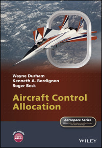
Cover photo: NASA's NF-15B research aircraft is shown during an early yaw-vectoring mission in the ACTIVE flight research project. Credits: NASA Photo
Dedication
For Craig Steidle, Bob Hanley, and John Foster. Thanks guys.
Series Preface
The field of aerospace is multi-disciplinary and wide ranging, covering a large variety of products, disciplines and domains, not merely in engineering but in many related supporting activities. These combine to enable the aerospace industry to produce innovative and technologically advanced vehicles. The wealth of knowledge and experience that has been gained by expert practitioners in the various aerospace fields needs to be passed onto others working in the industry and also researchers, teachers and the student body in universities.
The Aerospace Series aims to be a practical, topical and relevant series of books aimed at people working in the aerospace industry, including engineering professionals and operators, engineers in academia, and allied professions such commercial and legal executives. The range of topics is intended to be wide ranging, covering design and development, manufacture, operation and support of aircraft, as well as topics such as infrastructure operations and current advances in research and technology.
Modern aircraft are designed with multiple control surfaces, and possibly other control effectors e.g. thrust vectoring, and therefore problems can arise as to how to combine these control devices in an optimal manner, particularly in low-speed flight regimes where the aerodynamic surfaces lose their effectiveness.
This book, Aircraft Control Allocation, provides a detailed explanation of some selected topics relating to the aircraft control allocation problem. After providing some background material in aircraft control and control laws, a number of approaches that can be used to solve the control allocation problem are illustrated and the influence that they have on control law design discussed. Of particular note is the chapter describing some of the lessons learnt whilst designing the X-35 Flight Control System.
Peter Belobaba, Jonathan Cooper and Alan Seabridge
Glossary
Dot over quantity: the derivative with respect to time of the contents of the parentheses
.
Hat over quantity: the contents of the parentheses
are approximate.
Angle-of-attack: the aerodynamic angle between the projection of the relative wind onto the airplane's plane of symmetry and a suitably defined body fixed
-axis.
Sideslip angle: The aerodynamic angle between the velocity vector and the airplane's plane of symmetry.
,
,
Vector norms:
is the square root of the sum of the squares of the entries in the vector. It appears everywhere.
is the sum of the absolute values of the entries and
is the greatest absolute value.
and
frequently appear in linear programming problems.
Either:
Every combination of control effector deflections that are admissible; in other words, that are within the limits of travel or deflection.
A normally diagonal matrix used to specify the dynamics in a dynamic-inversion control law.
The effects, usually body-axis moments, moment coefficients, or angular accelerations, of every combination of control effector deflections in
, q.v. (sense 1). Sometimes called the AMS, for ‘attainable moment set’ or subset.
Bank angle: one of three angles that define a 3-2-1 (
-
-
) rotation from inertial to body-fixed reference frames.
Either:
(Primarily) A subset of the attainable moments (
) consisting of all the moments that are generated by a particular control allocation method.
A plane surface that arises in Banks' method of allocation for the three-moment problem.
Heading angle: one of three angles that define a 3-2-1 (
-
-
) rotation from inertial to body-fixed reference frames.
A subset of
: all admissible controls that a particular control-allocation method can return as solutions to a control-allocation problem.
Pitch attitude: one of three angles that define a 3-2-1 (
-
-
) rotation from inertial to body-fixed reference frames.
One of the matrices of the linearized equations of motion:
is the system matrix,
is control effectiveness matrix, and
is the output matrix.
The non-dimensional stability or control derivative of
with respect to
: it is the non-dimensional form of
.
Complementary: a superscript to certain dynamic responses.
Controllable: a superscript to certain dynamic responses.
,
Desired: a subscript to a dynamic response, or any other quantity.
Body-fixed reference frames. The origin is at the airplane's center of mass. The axes
and
lie in the airplane's plane of symmetry.
completes the right-hand system. Once defined, a body-fixed reference system's orientation with respect to the body does not change. Two frequently used body-fixed reference frames are the principal axes and the stability-axis system.
Local-horizontal reference frame. The axes
,
, and
are oriented north, east, and down, respectively. The earth is flat.
Wind-axis system. The axis
lies in the direction of flight, opposite the relative wind.
is in the plane of symmetry, oriented downward.
Either:
Acceleration of gravity, or
The non-dimensional units of load factor
, q.v.
With subscripts; moment of inertia.
Kinematic: a superscript to certain dynamic responses.
Lift, side force, and drag: wind-axis forces in the
−,
− and
−directions, respectively.
Body-axis moments about the
axis (rolling),
axis (pitching), and
axis (yawing), respectively.
Either:
Lift, or
Rolling moment, depending on context.
Lateral-directional, meaning all motions, accelerations, forces, and so on, that are not longitudinal, q.v. Sometimes
lat-dir
.
Longitudinal, meaning all motions, accelerations, forces, and so on, that take place in the airplane's plane of symmetry. Pitching moments, velocities, and accelerations are about the airplane's
-axis but the motion is in the
–
plane.
The mass of the airplane.
Load factor, the ratio of lift to weight,
. Measured in
s.
Body-axis roll rate, pitch rate, and yaw rate, respectively.
A generalized inverse of a matrix
:
and
, with appropriate dimensions.
Subscript, ‘evaluated in reference conditions’.
Vector of control effector variables.
,
Vector of control effector limits, minimum or maximum.
,
Vector of control effector limits, lower or upper. This notation seems preferred by linear programmers over
,
, q.v.
Names of body-axes.
A weighting matrix, generally diagonal and positive.
Names of wind axes.
Where
is a force or moment and
is a state or control, a dimensional derivative,
. It is the dimensional form of
, q.v. The definition does
not
include division by mass or moment of inertia. If
is a control effector the result is called a control derivative, otherwise it is called a stability derivative.
Body-axis forces in the
-,
- and
-directions, respectively.
Names of axes. With no subscripts usually taken to be body-axes.
ACTIVE
Advanced Control Technology for Integrated Vehicles. A research F-15 with differential canards, axisymmetric thrust vectoring, and other novel features.
ADMIRE
Aero-Data Model In a Research Environment, simulation code. See
Appendix B
.
Admissible
Of a control effector or suite of control effectors, those deflections that are within the physical limits of employment.
AMS
Attainable moment subset or set,
.
Angular accelerations
See Objectives.
ARI
Aileron-rudder interconnect. Normally used to reduce adverse yaw due to aileron deflection.
Attainable
Of moments or accelerations; that which can be generated by some admissible combination of control effectors. The term may be applied globally, meaning there is some theoretical combination, or locally, to a particular control allocation method, meaning those combinations of control effectors that the method will generate using its rules.
Basic feasible solution
Of linear programs, a basic solution to the equality constraints in a linear program that also solves the inequality constraints.
Basic solution
Of linear programs, a solution to the
linear equality constraints of a linear program in ‘standard form’ with
of the decision variables at their bound.
CAS
Control augmentation system.
Control effectiveness
A measure of the effect of utilizing a control effector, either moment, moment coefficient, or angular acceleration.
Control authority
The aggregate effect of the effectiveness of all the control effectors in whatever combination.
Control power
Angular acceleration per unit of control deflection.
CHR
Cooper–Harper rating; sometimes HQR.
Constraint
Of a control effector, a limiting position, usually imposed by the hardware. It may also refer to a limit on the rate of travel. In linear programming, a constraint may refer to the position limits, but also of an equality that must be satisfied. Thus
is an inequality constraint, and
is an equality constraint.
Control effector
The devices that directly effect control by changing forces or moments, such as ailerons or rudders. When we say ‘the controls’ with no qualification, we usually mean the control effectors. The sign convention for conventional flapping control effectors follows a right-hand rule, with the thumb along the axis about which the effector is designed to generate moments, and the curled fingers denoting the positive deflection of the trailing edge.
Control inceptor
Cockpit devices that control, through direct linkage or a flight-control system or computer, the control effectors. Positive control inceptor deflections correspond to positive deflections of the effectors they are connected to, barring such things as aileron–rudder interconnects (ARI, q.v.).
Cycling
Of a linear program, a condition in which a sequence of vertices is visited by a solver for which the objective function does not decrease, eventually returning to the starting point in the cycle. Cycling represents a failure to converge and must be addressed by choosing an exchange rule designed to prevent it.
Degenerate basic solution
Of linear programs, a basic solution to a linear program in which one of the
decision variables in the basis is at its bound in addition to the non-basic variables.
Decision variables
The set of unknown parameters being optimized in a linear program.
FBW
Fly by wire. The pilot flies the computer, the computer flies the airplane.
FQ
Flying qualities.
Ganged
Said of mechanical devices that are linked so that they move in fixed relation to each other, such as ailerons.
HARV
High angle-of-attack research vehicle.
HQ
Handling qualities.
HQR
Handling qualities rating.
Interior point method
One of a family of numerical methods that seek to find the optimal solution to a linear program by moving through the interior of the feasible set.
Intersection
Of two objects (q.v.), an object that is wholly contained in each of the two.
Lat-Dir
Lateral-directional.
LEU, LED
Leading-edge up, down. Terms used to describe the deflection of leading-edge control surfaces.
Linear programming
A problem, or the method of solving that problem, of optimization of an objective subject to linear equality and inequality constraints. To the purpose of this book, a method of allocating controls subject to position constraints.
Moments
See Objectives.
Moment coefficients
See Objectives.
Object
A generalization of any of the several polytopes that describe sets of admissible controls and attainable moments.
Objectives
Those which control effectors are intended to generate. Originally control allocation sought to find the control effectors that generated specified moments, or moment coefficients. Subsequently researchers have tended toward using angular accelerations as the objectives. We will generally speak of the objectives as being moments.
Object notation
A method of identifying objects (q.v.) using a 0 for a control at its lower limit, a 1 at its upper limit, and a 2 if it can be anywhere in between.
OBM
On-board model. A set of aerodynamic data for an aircraft stored in the aircraft's flight control computer.
Over-actuated control system
See Redundant controls.
Phase one/two program
Phase one of a linear programming solver solves a modified problem in order to locate an initial feasible solution for the phase two solver that will optimize the original problem.
PIO
Pilot-induced oscillation. There's a more politically correct term that removes the onus from the pilot.
PR
Pilot rating; sometimes HQR, q.v.
Preferred
Of a solution to the control allocation problem, a control effector configuration that is as close as possible to to one that is preferred. Minimum norm solutions are used as preferred solutions often.
Pseudo control
A combination of control effectors intended to create a certain effect, such as the excitation of a particular dynamic response mode of the airplane.
About the Companion Website
Don't forget to visit the companion website for this book:
www.wiley.com/go/durham/aircraft_control_allocation
There you will find valuable material designed to enhance your learning, including:
Simulation quick start guide
Scan this QR code to visit the companion website
Chapter 1Introduction
The general theme of the book is to reproduce the research and insights that led the authors through their seminal studies into airplane control allocation. There is much research remaining to be done in the field of control allocation, and by following the thinking that preceded the fruitful directions taken by other researchers, new areas of inquiry will be opened.
The authors defend their geometrical approach to visualizing the problem as one that provides greater insight into the mechanisms of the methods of solution that exist or may be contemplated. This is particularly true when considering the processes of reconfiguring the controls following the identification of a failure.
It is emphasized that the primary interest of the authors and the focus of the book is airplanes. Thus, we stick to a relatively small number objectives in the allocation problem, corresponding primarily to the three rotational degrees-of-freedom of airplanes and secondarily to the linear degrees-of-freedom. We acknowledge that there are many other fields that have similar problems, and believe our research lays a sound basis for other researchers to modify our results to apply them to their particular interests.
With respect to rigorous mathematical proofs, none will be found here. The authors are not mathematicians, as will be readily confirmed by any real mathematician who picks up this book. We certainly never thought before embarking on this research that ‘null space’ and ‘airplane’ would ever be used in the same sentence. We typically began by sketching a two-dimensional figure on the blackboard, something that seemed ‘intuitively obvious’ to us, and wondering if that figure generalized to higher dimensions.
Most important results have been proved in other sources: the many technical papers, theses, and dissertations that arose from our research, or in textbooks, particularly books that deal with linear algebra. Many of these publications are presented in Appendix C. Here we will just make claims that we are pretty sure are true. For instance, rather than prove that convexity is preserved under the mappings we describe, we will just assert it and perhaps give compelling evidence of its truth.
1.1 Redundant Control Effectors
The origins of our research into airplane control allocation lay in earlier research into model-following and dynamic-inversion control laws. The nature of model-following and dynamic-inversion algorithms is such that one is required to find a vector of control effector deflections that yield a desired moment, force, or acceleration. With three moments and three controls, the answer for a linear problem is a trivial matrix inversion. The physical limits of the control effectors does not affect the solution since the solution is unique. That is, for an airplane with ganged ailerons, a rudder, and an elevator, the combination of these effectors that will generate a specific moment vector is unique; if one or more saturates then the problem is not in the math but in the hardware.
Early problems arose when considering an airplane whose horizontal tails were not ganged to generate pitching moments only, but that could be displaced differentially as well to generate rolling moments and, unintentionally, yawing moments. By considering the left and right horizontal tails as independent we now have four control effectors for the three components of the moment vector to be generated. The linearized control effectiveness matrix (to be defined in Eq. (2.20)) is no longer square, but has three rows and four columns.
Figure 1.1 depicts a variety of control effector types. The airplane is USAF S/N 71-0290, the F-15 ACTIVE (Advanced Control Technology for Integrated Vehicles). The canards and horizontal tails are all-moving surfaces. The two vertical stabilizers have hinged rudders at their trailing edges. The wings have trailing-edge ailerons and flaps. Finally, both engines have axisymmetric thrust vectoring capabilities. Each of these various control effectors is capable of independent action.
Figure 1.1 F-15 ACTIVE
Redundant control effectors are employed to extend an airplane's performance envelope, typically in the low-speed regime. Thrust vectoring generates moments long after conventional flapping control surfaces have lost effectiveness at low dynamic pressure. Thrust vectoring enhances the dog-fighting potential of the F-22 Raptor, and permits maneuvers such as Pugachev's Cobra to be performed in other aircraft.
Clever control allocation is not needed in high-speed flight, where more than ample forces and moments can be generated with small effector deflections. In low-speed flight aerodynamic effectors lose effectiveness and must be combined with other effectors (aerodynamic or propulsive). However, if there are more control effectors than moments or accelerations to be generated, methods of allocating these controls are needed.
We are now faced with a ‘wide’ control effectiveness matrix: more columns than rows. As we will see there is a simple mathematical way to ‘invert’ such matrices. The real problem arises when the physical limitations of the control effectors are considered. In other words, control effectors have hard deflection limits that cannot be exceeded. When simple mathematical solutions to the problem are used, it is possible for one or more effectors to be unnecessarily commanded past its limits, meaning that it will saturate. When a control effector is saturated, the assumptions on which the flight control system was based are no longer valid.
1.2 Overview
We will begin by discussing aircraft flight dynamics and control. This will consist of a very brief overview of flight dynamics and its nomenclature, offered to provide the reader with explanations for some of the terms used subsequently.
Next we will spend some time describing dynamic inversion control. This form of control lends itself naturally to the control allocation problem as we have posed it. We will briefly discuss ‘conventional’ control, and even more briefly mention model-following control. All three forms of control law determination have some need of control allocation.
After formulating the problem, we address the geometry of control allocation. We do this first considering two-moment problems. Two-moment problems have application in aircraft control, since often the lateral-directional problem (rolling and yawing) is treated separately from the longitudinal problem (pitching). Moreover, it is much easier to make figures on the page of two-dimensional objects than of three-dimensional ones.
The geometry of the three-moment problem is a natural extension of that of the two-moment problem, and it is discussed in detail. For each of the two- and three-moment problems a metric is offered that permits comparison of different control allocation methods for their effectiveness in solving the problem. This gives rise to the idea of a ‘maximum set’ of moments that can be generated using different control allocation schemes, and its importance is discussed.
A large section on solution methods follows. We explore all the allocation methods of which the authors have first-hand experience, and most are accompanied by numerical illustrations. One of the control allocation methods—linear programming—is briefly discussed. Because of the current interest among researchers in the subject of linear programming solutions, there is a separate section (Appendix A) that further explores linear programming in greater detail.
All the preceding has been based on a global problem: the total set of control deflections that yield the whole moment vector. Now we turn our attention to a local problem. Digital flight control computers solve the allocation problem scores or even hundreds of times a second. We look within one frame of the computer's operation and consider not just how far an effector can move, but how fast. This permits us to incorporate rate limits into the problem. This framewise allocation comes with a serious drawback sometimes called ‘windup’. The remedy to windup is not hard and comes with some beneficial side effects.
Next we briefly explore control allocation and flight control system design. Example designs are given for a roll-rate command, pitch-rate command, and a sideslip controller. Finally, the consequences of using a non-optimal control allocation method are graphically displayed.
At the end of the text there is a chapter on some of the real-life applications of the previously described research. Lessons learned from the design of the X-35 control system are presented.
Throughout the book we occasionally make reference to simulation code. The MATLAB®/Simulink® based code is available at a companion website to this book, and it is fully explained in Appendix B. The simulation code offers different modules that implement the various control allocation methods described in the book. Readers are free to adapt and use this code to further explore the concepts of control allocation.
We feel that a common simulation source is essential to creating reproducible results. Many technical papers present simulation results with insufficient information about that simulation for the reader or reviewer to reproduce them. There are many assumptions inherent in one researcher's simulation code that cannot be conveyed in a brief paper but that may greatly affect the results one obtains.1 The simulation code we provide came to us courtesy of the Swedish Defence Research Agency with their permissions. MATLAB®/Simulink® code is available in student and academic editions and should be very widely accessible.
The final appendix is an annotated bibliography, in which we clean out our files of control allocation and dynamic inversion papers and list them, along with their abstracts or other descriptive material. This appendix is a good place to look to see if anyone is pursuing interests related to yours. It is inevitable that some have been overlooked, either through our inattention or the fault of some search engine or other. Our loosely-enforced cut-off criterion for inclusion in this list was that the source be refereed. Conference papers were generally not included unless the material was unique and relevant.
Finally, we wish to emphasize that the content of this book reflects only topics with which the authors are personally familiar. It is not a survey of the control allocation literature. There are many very good and sound areas of control allocation research that we have not addressed, except as indicated in the annotated bibliography (Appendix C). There one will find works by Marc Bodson, Jim Buffington, Dave Doman, Dale Enns, Tony Page, and many others with whom the authors have had collegial exchanges.
In particular we appreciate a group familiarly known as ‘Bull studs’: John Bolling, Josh Durham, Michelle Glaze, Bob Grogan, Matt Hederstrom, Jeff Leedy, Bruce Munro, Mark Nelson, Tony Page, Kevin Scalera, and the others who toiled in the ‘Sim Lab’ to help make sense of all this. And lastly Fred Lutze, who pondered the various stages of our progress and occasionally said, ‘You could do that, but it would be wrong.’
References
Aerodata Model in Research Environment (ADMIRE), Ver. 3.4h, Swedish Defence Research Agency (FOI), Stockholm, Sweden, 2003.
Bodson, M and Pohlchuck, E 1998 ‘Command Limiting in Reconfigurable Flight Control’
AIAA J. Guidance, Control, and Dynamics
,
21
(4), 639–646.
1
For example, whether one begins the calculations in a given frame assuming that the last commanded controls have been achieved, or using the actual deflections that resulted. It can make a big difference. Most of what this statement means will be made clear in
Chapter 7
. See Bodson and Pohlchuck (1998) for some more insight.
Chapter 2Aircraft Control
This chapter provides a brief overview of the subject of flight dynamics and control. Readers who are knowledgeable in the field will probably need only to resolve any differences between their notation and usage and ours (see the glossary for most of these). Our practices are based largely on those of Etkin (1972) and Etkin and Reid (1995). In particular we differ from many other authors in our definitions of stability axes (body-fixed), and of stability and control derivatives (no mass or moments of inertia).
2.1 Flight Dynamics
The usual derivation of the equations of motion of an airplane assume that it is a rigid body, and that an earth-fixed reference frame is inertial (the flat-earth assumption). The flat-earth assumption is justified in the present treatment because all the aircraft motions that we will consider will be limited to maneuvers at low speeds and of short duration, wherein the effects of centripetal, coriolis, and tangential accelerations due to the earth's rotation are negligible.
2.1.1 Equations of Motion
2.1.1.1 Kinematic Equations
The kinematic equations relate the angular accelerations of the airplane's body-fixed axes to the rate of change of its orientation with respect to the local horizontal reference frame. This representation may be done using Euler angles, Euler parameters, direction cosines, or any suitable characterization. Here we use Euler angles. The derivation is straightforward, and results in Eqs. (2.1).
The angles , , and are the names of the Euler angles that are defined in a 3-2-1 (, respectively) rotation sequence from an earth-fixed reference frame to a body-fixed reference frame. They are called the heading angle , pitch angle , and bank angle . Note that with the flat-earth assumption these angles are the same as in transforming from a local horizontal system. Also note that Eqs. (2.1) are invalid if (pointed straight up or straight down).
The angular rates , , and are the components of the inertial rotation rate of the body-axes, as represented in body-fixed coordinates. They are called the roll rate , pitch rate , and yaw rate . The vector of inertial rotation rates is denoted , and that vector has components in the body-fixed coordinate system , , and .
From a flight dynamics perspective, Eqs. (2.1) are needed to keep track of the orientation of the gravity vector with respect to the airplane.
2.1.1.2 Body-axis Force Equations
The body-axis force equations are the rates of change of the inertial components of velocity, as seen in the body-axes:
In this expression is the inertial velocity of the airplane's center of mass. The subscript in means that the derivative with respect to time of is taken with respect to the body-fixed coordinate system. Everything within the curly braces defines a vector, and the other subscript outside the braces means this vector is represented, or has components in, the body-axis system.
The parameter is the mass of the aircraft. The vector consists of forces (aerodynamic), (thrust), and (the weight of the airplane) acting on the airplane.
The components of are named simply , , and . The thrust vector has been assumed to have components , , and , to accommodate controlled thrust vectoring. The components of arise from a simple transformation of the local-horizontal -axis into body-fixed coordinates.
The body-axis forces are related to lift (), drag (), and side force () through a transformation
The matrix replaces the cross-product operation ,
As a result we may write the body-axis force equations,
2.1.1.3 Body-axis Moment Equations
The body-axis moment equations are the equations of primary interest in control allocation. In terms of the rates of change of the inertial components of angular rotation, as seen in the body axes, these are
The meaning of is analogous to that for , above. The derivative is taken with respect to the body-fixed reference frame, and the components of the resulting vector are represented in the body-fixed frame. is the inertia matrix of the airplane.
The externally applied moments are those due to aerodynamics and thrust (gravity acts through the center of mass, the origin of our coordinate system, so there are no moments due to weight). On aircraft with controlled thrust vectoring, moments about all three axes may be produced. As a result the moments are
We assume a plane of symmetry, so in the inertia matrix the cross-products involving become zero,
The inverse is then given by
Here, . The resulting moment equations are given by Eqs. (2.12)
If the problem is posed in principal axes, then Eq. (2.12) is greatly simplified:
2.1.1.4 Body-axis Navigation Equations
The position of the aircraft relative to the Earth may be found by representing the velocity in Earth-fixed coordinates and integrating each component.
We usually know the transformation from local horizontal to body, , in terms of the roll angle , the pitch angle , and the heading angle .
From the properties of direction cosine matrices we have . In other words, the transpose of is the transformation from body to local horizontal. Expanding the equations,
2.1.1.5 Wind-axis Relationships
A complete set of differential equations may be derived using the wind axes, but the result is more complicated than that for body axes. However, if none of the forces and moments is functionally dependent on or (a mathematical contrivance at best) then a somewhat simpler approach is possible. We may relate , , and directly to the body-axis force equations, based on the definitions of the wind-axis quantities , , and .
The expression is best formulated in terms of and
2.1.1.6 States of the Airplane
Each term in the equations of motion that appears as a time-derivative is a state of the airplane. Thus there are twelve states: three positional (, , and ), three angular (, , and ), three velocity (, , and ), and three angular velocity (, , and ). The wind-axis variables , , and may be used in lieu of the body-axis velocities , , and .
In the equations of motion there is a nonlinear ordinary differential equation for every state, expressed in terms of the states themselves, of forces and moments, and of many other variables not related to the control deflections.
2.1.2 Linearized Equations of Motion
The nonlinear equations of motion presented in Section 2.1.1 generally do not have analytical solutions. In the forms given they may be used in flight simulation using numerical integration.
Normally in a course in flight dynamics it is at this point that the nonlinear equations are linearized and placed in a form amenable to analytical solution. In this book we will not be concerned with such solutions, but we will have need of the linearized effects of the control effectors, so we will briefly describe the process of linearization.
Associated with the linearization process, there is usually a reference flight condition, and it is normally a steady condition. Linearization is accomplished by retaining just the first-order terms in a Taylor series expansion (or Maclaurin series with suitable definitions). The process can become somewhat convoluted, since there are explicit dependencies as well as assumed dependencies; that is, the dependencies of the forces and moments on the states and controls.
In this book we will have no need of the complete linearized equations of motion, but we will extensively use the linearized control effectiveness with respect to the three moments, or values related to the three moments. The quantities of primary interest are moments, moment coefficients, or angular accelerations in the kinematic equations. Unless we are talking about one or the other of these values specifically we will use a generic symbol with a subscript to indicate the axis. Likewise, in a general discussion we will refer the effects simply as moments.
Moment coefficients are obtained from the moments by non-dimensionalization. This consists of division by the dynamic pressure, the wing area, and a characteristic length. The wing area is denoted by . The dynamic pressure, , is a function of air density and airspeed ,
The characteristic length is a suitably defined chord length for the pitching moment, and the wing span for the rolling and yawing moments. The non-dimensional coefficients are then
In Eqs. 2.12 and 2.13 the one-to-one correspondence between the angular accelerations and the moments is made clear. The moments and related effects are summarized in Table 2.1.
Table 2.1 Moments and related effects of control deflections
Axis
Moment
Moment coefficient
Angular acceleration
Generic


