18,49 €
Mehr erfahren.
- Herausgeber: The Crowood Press
- Kategorie: Fachliteratur
- Serie: Crowood Metalworking Guides
- Sprache: Englisch
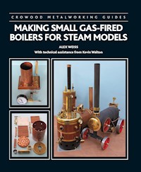
This book describes how to make two vertical and two horizontal copper boilers with a capacity of less than three-bar litres. All four boilers are heated with liquid petroleum gas (LPG) contained in small refillable or disposable tanks. With over 285 colour photographs and diagrams, it includes the tools and equipment required, together with important safety considerations; how to work the various materials to make the necessary parts; step-by-step instructions on the technique of silver solder; the testing regime; a review of various sizes and shapes of gas burners and how to connect them; instructions for building replacements for the well-known Verto boiler, a vertical boat boiler, a portable-engine boiler and a Cornish boiler with Galloway tubes. Finally, there is guidance on the efficient operation and essential maintenance of steam boilers and safety calculations and a list of useful contacts.
Das E-Book können Sie in Legimi-Apps oder einer beliebigen App lesen, die das folgende Format unterstützen:
Seitenzahl: 260
Veröffentlichungsjahr: 2021
Ähnliche


CROWOOD METALWORKING GUIDES
MAKING SMALL GAS-FIREDBOILERS FOR STEAM MODELS
There is comprehensive information in this book that explains how to build all four of these boilers.
CROWOOD METALWORKING GUIDES
MAKING SMALL GAS-FIREDBOILERS FOR STEAM MODELS
ALEX WEISS
With technical assistance from Kevin Walton
First published in 2021 byThe Crowood Press LtdRamsbury, MarlboroughWiltshire SN8 2HR
This e-book first published in 2021
© The Crowood Press 2021
All rights reserved. This e-book is copyright material and must not be copied, reproduced, transferred, distributed, leased, licensed or publicly performed or used in any way except as specifically permitted in writing by the publishers, as allowed under the terms and conditions under which it was purchased or as strictly permitted by applicable copyright law. Any unauthorised distribution or use of this text may be a direct infringement of the author’s and publisher’s rights, and those responsible may be liable in law accordingly.
British Library Cataloguing-in-Publication DataA catalogue record for this book is available from the British Library.
ISBN 978 1 78500 877 1
Disclaimer
Safety is of the utmost importance in every aspect of metalworking. The practical workshop procedures and the tools and equipment used in metalworking are potentially dangerous. Tools should be used in strict accordance with the manufacturer’s recommended procedures and current health and safety regulations. The author and publisher cannot accept responsibility for any accident or injury caused by following the advice given in this book.
Cover design: Maggie Mellett
Contents
Acknowledgements
Introduction
1Materials and Working Them
2Silver Soldering
3Testing Boilers
4Boiler Fittings
5Heating the Boilers
6Replacement Verto Boiler
7Vertical Boat Boiler
8Portable Engine Boiler
9Cornish Boiler
10Operating your Boiler
Conclusions
Appendix 1 – Safety Calculations
Appendix 2 – Useful Contacts
Index
Acknowledgements
Much of this book was written during the coronavirus pandemic and covers four boilers that I built together with my friend, Kevin Walton; fortunately not during the UK lockdown. These boilers all meet the UK three-bar litre requirements of the UK2018 Boiler Test Code 2018 Volume 2. All four are heated by ceramic burners, again built by Kevin and myself, although you can just as easily heat them with commercially purchased ceramic burners.
It is pretty clear that when the pandemic comes to an end, the market place, including the model engineering one, is likely to have changed. Some businesses will have prospered; sadly some will have ceased trading. In addition, global trading arrangements and exchange rates will inevitably have changed, affecting the price of many of the materials and finished items we purchase. For those who use eBay for purchasing parts for model engineering, try and use suppliers you have bought from before. Particularly for more expensive items, take great care if you have not used the company before and do your best to check their reputation. And those of us who may continue to work from home will find that we have more spare time that was previously spent commuting to and from work. We will all have to do our best to benefit from the changing environment.
I must thank Kevin Walton, who has provided much of the technical input and detailed recommendations, also making parts and helping with the assembly, which have made possible the building of the boilers that I have described in this book. He has also helped solve some significant issues about how best to design them and build them.
Finally, I must mention my wife Lynda, who daily has had to put up with all the time I spend in my workshop, Kevin’s workshop, building, testing, running and photographing the boilers from kits of parts to completed items. Inevitably this is followed by months writing up and organizing the results on my computer ready for publication by the friendly staff at The Crowood Press.
It goes without saying that any errors in this book are mine and mine alone.
Introduction
For millennia after human beings first harnessed horses and other beasts of burden, the ability to power machines and move people and goods remained very limited. Goods were transported on land by horse and cart, while at sea wind power or men rowing were the only choices. Early water mills were built by the Greeks and Romans over 2,000 years ago to grind grain. Later, the first windmills were built to assist in making flour and pumping water for crop irrigation. Designs of windmill with a vertical axis were developed in Persia (now Iran) in the second half of the first millennium AD. However, the amount of power available from wind was relatively modest when compared to the size of the machinery. Later, water mills were built but in both cases the locations were tied to places where water or wind was abundant and in times of drought or calm weather neither source would produce any useful power. This problem still applies to several ‘green’ technologies.
However, when effective steam engines with boilers to power them were developed to remove water from mines and eventually to replace these wind- and water-powered machines as well as horses, their power output was, unsurprisingly, measured in horsepower: a unit of measure in today’s metric system specified in watts and kilowatts.
Fig. 2 Two horsepower of effort ready to pull a farm implement. This is the equivalent of around 1½kW.
In eighteenth-century Britain there was access to both coal and iron beneath the ground, allied to a relatively liberal form of democratic government. These factors provided the opportunity for forward-thinking men endowed with creativity and an engineering aptitude to start developing a ‘mechanical horse’. It was the dawn of the Industrial Revolution in the UK that spurred engineers such as Thomas Newcomen, Richard Trevithick and James Watt to develop revolutionary solutions for draining water from mines that supplied industry with metal ores and coal for powering the spinning jennies and looms in the cotton mills.
EARLY BOILERS
The first designs were atmospheric engines where the very low-pressure steam from a primitive boiler was condensed in the cylinder by spraying in cold water. Atmospheric pressure on the top of the piston created the movement that provided the power. Even with a perfect vacuum in the cylinder, the pressure on the piston could never exceed 1 bar or 14psi and was unlikely to get anywhere near these figures. Early engines only produced a reciprocating motion, which was ideal for pumping water out of mines. The invention of the crank, and other solutions to avoid early patent problems, resulted in steam engines that provided rotary motion; a useful step forward towards practical steam vehicles, together with significant boiler improvements. The earliest boilers were simply pots, known as haystack boilers; a facsimile of one of these is shown in Fig. 3. They all ran at very low steam pressures of 2 to 3psi (0.14 to 0.2bar).
Fig. 3 A replica of a haystack boiler showing the cast-iron plates riveted together to form a dome, embedded in a brick structure, which enclosed the fire.
Fig. 4 A line drawing that clearly shows the shape of a wagon boiler that was still not good at containing any significant degree of steam pressure.
With the development of the true steam engine, rather than the atmospheric engine, more steam at a higher pressure was required and the haystack boiler morphed into the wagon boiler that could run at twice the pressure; not a great increase! The fundamental weakness of this type of boiler was its shape, shown in Fig. 4, and this became clear as pressures increased. Richard Trevithick concluded that the only practical shape for higher pressures was a round cross-section. Thus around the end of the eighteenth century, as rolled iron plates became available, the construction of boilers moved toward a form we would recognize today; a cylindrical boiler with domed ends.
The steam engine and steam boiler had to work together and initially they formed a single system but as designs improved they were located separately. At first there were no health and safety rules when operating boilers. The dangers of steam pressure were unknown, resulting in quite a few fatal boiler explosions. Construction methods were primitive and boilers were built from separate cast-iron parts held together with countless solid rivets. Early boiler pressures were remarkably low but in 1802 Richard Trevithick ran a stationary engine at 145psi (10bar), an unprecedented pressure for the era and considered very dangerous by many.
Fig. 5 Trevithick’s dredger engine, which integrated the engine and boiler into a single structure. At last the boiler was cylindrical, enabling it to contain so called high-pressure steam. This view shows the fire door and chimney end.
Trevithick’s 1804 Cornish boiler was the starting point of modern boiler practice; it was cylindrical with a large circular fire tube running through the centre. It was an excellent shape to resist the internal steam pressure. Fig. 5 shows the boiler/engine combination of his dredger engine. Unfortunately its large fire tube reduced the space for steam at the top of the boiler, leaving only a shallow depth of water above what was inevitably the hottest part of the fire.
Fig. 6 The Lancashire boiler at Crofton pumping station is still run regularly with fires in both flues.
In the middle of the nineteenth century, William Fairbairn patented the Lancashire boiler. This design used two smaller fire tubes rather than the one large tube in the Cornish boiler. These smaller tubes increased the size of the fire grate and area of the heating surface, while at the same time allowing a greater depth of water over the fire tubes. Fig. 6 shows the Lancashire boiler at Crofton pumping station, which is still used to raise steam. As early as 1848, W. & J. Galloway, based in Manchester, patented the Galloway tube, a tapered thermic syphon water tube inserted in the flue of a Lancashire boiler. They also became a feature of many Cornish boilers. Of the several variations to the Lancashire boiler, by far the most effective was the fitting of Galloway tubes in the flues in 1851. This involved installing a number of water tubes across the flue to increase the heated area of the water.
The Scotch boiler was another variation of the Cornish boiler with return-flow fire tubes added. This allowed more rapid steam raising and also improved efficiency, albeit at the cost of increased initial and subsequent maintenance costs.
The desire for vertical boilers was often driven by lack of space to install horizontal ones; particularly a problem at crowded industrial sites in the cities that provided the workforce for the various types of business that required steam power such as cotton and textile mills. Vertical boat boilers also became popular during the Victorian era as they occupied less hull space than their horizontal equivalents.
Steam engines and their associated boilers became the major sources of power for the eighteenth and nineteenth centuries and were a key part (together with the ready availability of raw materials) of the Industrial Revolution. They were soon developed into light enough machines to be used in a number of mobile applications, initially in horse-drawn appliances such as portable engines that could be moved around farms to the place where power was required and in fire engines where the steam engine pumped water on to the fire. The problem with self-powered road vehicles was the appalling state of the highways, which after a little rain became quagmires of mud. Fairly quickly, locomotives, and much later as the state of road surface was improved, traction engines, lorries and even a few cars were steam powered.
Fig. 7 Portable engines were popular before the advent of practical traction engines. This is an over-type example with the engine mounted on top of the boiler. The portable engine was towed to location by horses and provided steam power to a variety of farm machinery.
Fig. 8 A replica of the locomotive Puffing Billy at the Beamish museum, which runs beautifully along a track at the museum. The original was completed in 1814 and worked at a colliery near Newcastle upon Tyne until 1862.
The situation on ships was difficult because they were largely of wooden construction and at first the driving source was a paddle wheel. It was not until the creative Brunel built the SS Great Western in 1838 that transatlantic travel became a possibility. It was another year before the first ship was driven by a propeller rather than paddle wheels; a change that significantly improved efficiency.
On the health and safety front, it is interesting to note that the Factory and Workshop Act 1901 stated that steam boilers should have a proper safety valve, steam gauge to show the steam pressure and water gauge to show the depth of water in the boiler. Each boiler had to be thoroughly examined by a competent person at least once every fourteen months.
Reciprocating steam engines continued to provide sterling service until the middle of the twentieth century, by which time high labour costs, the length of time taken to fire and build up sufficient steam pressure in the boiler allied to the much better efficiency of internal-combustion engines resulted in their final demise. Despite this, boilers and steam turbines are still in widespread use in power stations to generate electricity, though a lot are being replaced by wind- and solar-generated electricity.
BOILERS TO BUILD
This book explains how to construct four boilers featuring three different configurations, all heated by LPG- (liquid petroleum gas) powered ceramic burners. None is particularly difficult to make. All the boiler bodies are constructed from a single length of seamless copper tube.
Regardless, construction work is straightforward and, because all the boilers fall within the 3bar litre testing limit, testing them is less onerous than for boilers with a larger capacity. All four boilers are capable of providing an excellent rate of steam production.
The book describes two vertical boilers; a 3½in (89mm) diameter tall one that is intended as a replacement for the original Verto boiler, which was part of a scale-model boiler/engine combination, and a short 108mm fire tube boiler specifically designed to provide power for model steam launches. Both of these vertical boilers incorporate a number of vertical fire tubes.
While neither of the two horizontal boilers is a scale model, the first is representative of an under-type portable engine with a horizontal fire tube boiler. It could also form the basis for a small-gauge locomotive or steam vehicle. The general arrangement drawing of the portable engine boiler shows the way the fire tubes are located.
Fig. 9 Chapters 6 and 7 provide complete information on how to build both the Verto and the 108mm boat boilers. The funnel of the Verto is standing beside the boiler and simply plugs into a fitting on top of the boiler.
Fig. 10 Chapters 8 and 9 describe in full the construction details of both the portable engine boiler and the Cornish boiler.
Fig. 11 The shape of the boiler and firebox for the portable engine boiler show how easily you could use it as the basis for a range of other applications such as a small locomotive or traction engine.
Fig. 12 Side and under view of the boiler for the portable engine boiler showing the layout of the fire tubes.
The other boiler could be classified as a Cornish single-flue boiler with Galloway tubes. The Cornish boiler has Galloway tubes in its flue so that water flows through them to increase the surface area exposed to heat. In the mid-nineteenth century, W. & J. Galloway inserted their Galloway tubes in the flues of a Lancashire boiler. They also became a feature of many Cornish boilers. Despite the fact that Galloway tubes in full-size boilers used tapered water tubes, for small model boilers, a parallel Galloway tube is quite satisfactory in a model and is easily sourced. However, this boiler does require quality step soldering of the flue and its Galloway tubes before this component is built into the complete boiler.
All the boilers are relatively small and are heated by easily removed ceramic burners. Providing the amount of water they hold multiplied by the steam pressure is less than three bar-litres, some of the most demanding independent test rules are circumvented. The boilers described all operate below the three bar-litre requirement. For example, operating with a water capacity of one litre means the pressure must not exceed 3bar (42.5psi), while with a capacity of 800ml, the pressure may be increased to 3.75bar (54psi).
You should understand that independent testing is needed for public operation of any of these boilers; model engineering clubs can usually provide access to an inspector. The rules applying to small boilers with a capacity of less than 3bar/litres are significantly less strict than those for larger boilers. They are described in the UKBoiler Test Code 2018 (Volume 2).
These boilers run at temperatures up to 140ºC, so it is vital to employ silver soldering for their assembly. Soft solder is simply not an option! Thus, you will need access to a brazing torch to build any of these boilers. Construction of the boilers assumes that you, the builder, have basic model engineering skills including:
◆Working from dimensioned figures.
◆Cutting, drilling, turning and milling copper, bronze and brass and the odd steel components.
◆Assembling components and silver soldering them together.
◆Pickling and cleaning items you have silver soldered together.
◆Bolting, fixing and gluing various parts to the boiler.
◆Installing and sealing in place the various boiler fittings. You could make some of these yourself.
Building any of the model boilers in this book is much less expensive than buying a ready-built boiler. Nor is it a particularly difficult task. It is an ideal project to follow the construction of a simple single- or twin-cylinder slide-valve engine from castings. It is hoped that this book will encourage more boiler building so that small engines can steam in a realistic manner rather than just be run on compressed air. It also provides an excellent lead into the construction of much larger boilers with capacities significantly bigger than 3bar litres.
BOILER TYPES
This book covers the construction, test and operation of two vertical fire tube boilers and two very different horizontal ones, which are suited to a variety of applications. Each one was intended for a particular purpose and customized to meet that role.
3½in (89mm) Verto Boiler
This vertical fire tube boiler is a replacement for the scale Verto’s original Woodroffe boiler, which is no longer available as a ready-made unit. It is more efficient and simpler to construct than the original design. The part of the boiler filled with water is 178mm tall and houses ten 8mm fire tubes, providing a good area of copper for heat transfer. A round 54mm ceramic burner provides the heat. There is a longer gauge glass than on the original boiler and a threaded connector to fit a clack valve for feeding water into the boiler. The water capacity is 800ml, meaning you could steam this boiler at 3.75bar (54psi). However, a better setting for normal use is 3.45bar (50psi).
Fig. 13 The replacement for the original Verto boiler is a reasonable replica and will happily steam the original engine.
4¼in(108mm) Vertical Boat Boiler
This vertical boiler is of a similar design to the 108mm boiler shown in Fig. 14 but 63.5mm shorter and has a lighter brass top cover. The result is a significantly lower centre of gravity; a key advantage for marine use. The boiler has a relatively small water capacity of 620ml, so the theoretical useable maximum pressure is up to 4.84bar (70psi). As the recommended hydraulic test is at 8.28bar (120psi), you should set your safety valve to 4bar (58psi), which is more than enough to power a twin-cylinder marine engine. The empty boiler itself weighs 2,245g. Fitting a mechanically or electrically powered boiler feed pump is a very good idea to keep the boiler water level up. Again, the boiler will produce sufficient steam for a small twin-cylinder engine.
Fig. 14 An early 108mm boiler designed and built by the author that has a water capacity of 900ml and a total weight of 3,150g.
Fig. 15 The 108mm vertical boat boiler will look the part in any model of a Victorian steam launch that needs an upright boiler.
3in (76mm) Portable Engine Boiler
This boiler was designed for use as a portable engine but also could be suitable for use as the basis of a small locomotive, traction engine or lorry. Its fire tubes run from a tube plate at the smokebox end through the boiler shell at the other end to a separate firebox below the boiler shell. This approach considerably simplifies boiler construction, although there is still a need for very simple step soldering to tack the firebox fire tubes in place. A rectangular ceramic burner is mounted in the firebox with secondary air fed, from the two slots in the base plate and the rear, into the firebox.
Fig. 16 The finished portable engine is a fun model that is self-contained and thus is relatively easy for you to steam.
The model has a 3in (76mm) diameter boiler, which is 254mm long. With a 38mm long smokebox, the 216mm long water chamber has nine 8mm fire tubes that are bent through 90 degrees. Its capacity is 830ml, so it can run an engine at up to 3.6bar (52psi). You would probably do better to set the safety valve to 3.45bar (50psi).
The complete model as described was fitted with a small underslung single-cylinder oscillating engine and employed two large rear wheels and two smaller steerable ones at the front. There is no reason why you should not install a different engine or fit it on top of the boiler in the more commonplace over-slung engine configuration. You could also use different wheels or make your own.
108mm Cornish Boiler
Although this 108mm horizontal boiler was originally designed for use in a Clyde Puffer steam boat, it has proved very satisfactory in a static role on land. The boiler shell is 132mm long with another 75mm added for the burner and connection to the funnel giving a total length of 208mm. A single 35mm flue is fitted with eight 8mm Galloway tubes. Its water capacity is 700ml, enabling it in theory to operate at pressures up to 4.28bar (62psi). In practice this is too high a figure as it is more than half the hydraulic test level, so set the safety valve to 4bar (58psi).
Fig. 17 The completed Cornish boiler is an elegant unit that does not occupy a great deal of floor space.
The boiler is heated by a 35mm ceramic burner that fits on the end of the flue, with an elbow at the other end of the flue to feed the products of combustion up the ship’s funnel. It provides sufficient steam to operate a small twin-cylinder slide or piston-valve engine. However, it is equally suitable for powering a stationary steam engine either on an ad-hoc basis or built into a model of a workshop, mill or factory.
WORKING PRESSURES
All the steam boilers described in this book can work at a pressure of at least 40psi or 2.75bar and for several of them a somewhat higher figure is also quoted. While the required boiler pressure depends on the engine you will power from it, most engines that are matched to one of these boilers will work well at this pressure or often an even lower one.
While the highest design working pressure for each of the boilers is described, you should normally set the safety valve below the maximum operating pressure of the particular boiler and one that suits the engine it is powering. If in doubt, set it to 40psi or 2.75bar. This means you must hydraulically test the boiler to twice the working pressure, 80psi or 5.5bar before you use it to generate steam. However, all the boilers in this book were hydraulically tested to 120psi (8.3bar) in order to provide an additional safety factor and it is recommended that you also test any boiler you build to this figure.
TESTING
The rules in The Boiler Test Code 2018 (Volume 2) state that small boilers below 3bar litres require independent testing and certification. They are exempt from some of the requirements of the much longer Volume 1 of the code, which deals with boilers from 3bar litres up to 1,100bar litres. Fortunately, none of the boilers in this book need to meet the Volume 1 rules.
You will have to hydraulically test and then steam test your new boiler before you use it to power a model. It will also need the maximum operating pressure marked on the pressure gauge and the safety valve checked at maximum burner heat to ensure the boiler pressure does not go above its operating limit. Using a boiler at an organized club or any other public place always requires independent testing and certification for safety and insurance reasons. Examples include the Association of 16mm Narrow Gauge Modellers and the Model Power Boat Association.
You can get your boiler tested quite easily if you join a club or are already a member. An authorized independent tester, found in most model engineering clubs, will do the testing and issue you with a certificate, which you must renew each year if you continue to steam the boiler. You will need to carry the test certificate with you and a certificate of insurance. You also need to check the condition of your boiler and steam test it once a year if you are using it regularly. And you will have to carry out a hydraulic test every four years.
Fig. 18 This home-made boiler pressure test rig is based on a hand-operated boiler feed pump and a 55mm pressure gauge that reads up to 160psi (11bar).
If you will use your boiler only for home running it does not require independent testing. However, it is in your interests to meet the rules for The Boiler Test Cove 2018 (Volume 2) even if you never steam in public. Thus, you should either get a friend to carry out the hydraulic and steam tests or do them yourself. And the test pressure is readily achieved with a mechanical boiler feed pump and a 50mm diameter pressure gauge like the one shown in Fig. 18. And do remember to record your test results.
HEATING SMALL BOILERS
By far the most practical source of heat is a mixture of liquid petroleum gases (LPG) that you can easily buy in small disposable cans. These usually contain a mix of propane, butane and isopropane. You can feed the gas to a suitable circular or rectangular ceramic burner that will fit the boiler firebox or its flue. All four boilers are heated by ceramic burners. You can economically build ceramic burners to fit each of the boilers. These are described in Ceramic Burners for Steam Boilers also published by Crowood Press. Building these burners is an ideal introduction to silver soldering prior to building a boiler. Chapter 9 describes a small rectangular burner specifically designed to fit in the portable boiler firebox. However, you can also fit suitable sizes of commercial burners into any of the boilers described.
Fig. 19 A throwaway LPG gas can is ideal for powering burners and needs a valve screwing to the output connection as well as gas pipe to the gas jet holder. These cans come in a variety of sizes; C100, C250 and C500 sizes are popular.
Fig. 20 You can either make a custom-size rectangular burner for the portable engine firebox or you can install a commercial rectangular one that will fit in the firebox and measures some 64mm × 45mm × 25mm.
If you wish to operate your boilers in a radio-controlled boat without a boiler feed pump, it is essential that the gas capacity is exhausted before the water in the boiler reaches the low safe limit; about one quarter full. You can buy small refillable gas tanks for this purpose. Although not recommended, you can home build such tanks. However, serious independent testing to 400psi (27.6bar) is then essential. You will also need to time how long the gas in your tank will last and whether this matches the amount of water available in the boiler that will be turned to steam.
USING A SMALL BOILER
It is important that if you are going to steam an engine, that its steam consumption matches the output of the boiler. The connection from the boiler to the engine needs to run via a lubricator and you may also want a connection to a gas control valve, especially if you plan to fit the boiler/engine combination in a boat, locomotive or vehicle. If your boiler is installed in a boat, you will need an oil separator to avoid causing pollution. Chapter 10 gives details of how to build one. You will need to learn how to fill a boiler, light the ceramic burner and steam your chosen engine to best advantage. There are examples in Chapter 10 of a number of the boilers operating a selection of steam engines, both large and small.
STEAM CAPACITIES
Any steam engine will fairly rapidly consume steam from its boiler. This will depend on the size and capacity of engine, the type of valve gear it uses (oscillating engines tend to consume a lot of steam), the load it is driving at what speed and whether the engine is running continuously or in stop/start mode. Steam turbines are also notoriously steam hungry should you wish to power one.
A boiler’s steam capacity mainly depends on the surface area of the water exposed to heat, its operating pressure and the amount of heat the burner is producing that is heating the water. The amount of time that the boiler can continue to provide steam will depend on its water capacity and whether it is replenished by a boiler feed pump. Thus it is important to match your engine and boiler/burner combination if you are to get a satisfactory level of performance from the combination. Appendix 1 gives some theoretical information to help you calculate steam consumption of your chosen engine.
COST OF BUILDING A BOILER
The cost of making a boiler depends on several factors:
1.The price of the materials. These include copper, bronze, brass and silver solder.
2.Whether you make or buy the fittings.
3.The cost of the various fittings if you buy them ready made.
4.Whether you need to acquire brazing equipment.
For a 108mm diameter horizontal copper boiler, the material cost, including a set of ready-made fittings, roughly equals the cost of the basic castings for a quality twin-cylinder, slide-valve engine it might power. And the fittings account for at least half of this cost. This assumes that you already have brazing facilities in your workshop. Of course, you can exchange price for time if you are prepared to make your own fittings.
It is worth noting that this information was correct at the end of 2019 before the coronavirus pandemic. As the world returns to a degree of normality, raw material prices may have changed as may exchange rates, import tariffs and the margins charged by traders.
SAFETY PRECAUTIONS
You will need to familiarize yourself with the various risks and dangers involved in boiler building and operating a boiler. It is important to use your common sense and to assess what are the potential risks. These are mainly the danger of starting an unwanted fire or of burning yourself when assembling your boiler. The risks when using a boiler are mainly associated with the management of small tanks of LPG. Thus it is sensible to ensure you have a fire extinguisher and a first-aid kit handy and ready for use. For preference, try not to work alone on brazing a boiler. A second pair of hands can prove very helpful.
Liquefied Petroleum Gas


