22,49 €
Mehr erfahren.
- Herausgeber: Crowood
- Kategorie: Lebensstil
- Sprache: Englisch
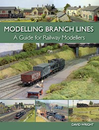
This comprehensive book is aimed at all those railway modellers who wish to create a realistic model of a branch line. First of all it examines the origins, developments and future of branch lines in Britain and then provides useful insights into how to select a suitable branch line to model. It discusses in detail how to create scenic realism and an appropriate setting for the model, with reference to the landscape, the infrastructure, the lineside and the use of authentic colour. Detailed information about a selection of several real, and some fictitious, branch lines are presented in order to inspire the modeller and help him to select a suitable subject to lovingly recreate. Finally, track plans and superb drawings of the whole scene are shown which provides the modeller with a visual intepretation of what the completed model should look like.
Das E-Book können Sie in Legimi-Apps oder einer beliebigen App lesen, die das folgende Format unterstützen:
Veröffentlichungsjahr: 2015
Ähnliche


MODELLING BRANCH LINES
A Guide for Railway Modellers
DAVID WRIGHT
THE CROWOOD PRESS
First published in 2015 by
The Crowood Press Ltd
Ramsbury, Marlborough
Wiltshire SN8 2HR
www.crowood.com
This e-book first published in 2015
© David Wright 2015
All rights reserved. No part of this publication may be reproduced or transmitted in any form or by any means, electronic or mechanical, including photocopy, recording, or any information storage and retrieval system, without permission in writing from the publishers.
British Library Cataloguing-in-Publication Data
A catalogue record for this book is available from the British Library.
ISBN 978 1 78500 020 1
Disclaimer
Power tools, glues and other tools and equipment used to create model scenery are potentially dangerous and it is vitally important that they are used in strict accordance with the manufacturer’s instructions. The author and the publisher do not accept any responsibility in any manner whatsoever for any error or omission, or any loss, damage, injury, adverse outcome, or liability of any kind incurred as a result of the use of any of the information contained in this book, or reliance upon it.
Photographs by the author unless credited otherwise.
Dedication
I would like to dedicate this, my third book, to my wife Karen.
Acknowledgements
I would like to express my special thanks to Martin Nield, John Hastings-Thomson, Phil Waterfield, Clive Baker and Rob Milliken. Their kind assistance and photographic and other contributions to this book have been invaluable.
CONTENTS
INTRODUCTION
CHAPTER ONE: MAKING A START
CHAPTER TWO: FINDING THE SPACE TO HOUSE YOUR MODEL BRANCH LINE
CHAPTER THREE: CREATING THE BRANCH LINE SETTING
CHAPTER FOUR: SELECTING A PROTOTYPE BRANCH LINE
CHAPTER FIVE: MODELLING FICTITIOUS BRANCH LINES
CHAPTER SIX: BRANCH LINE MODELLING PROJECTS
CHAPTER SEVEN: ADDING COLOUR TO THE MODEL BRANCH LINE
APPENDICES:
SUPPLIERS OF EQUIPMENT, KITS AND OFF-THE-SHELF MODELS
SOCIETIES, MUSEUMS AND HERITAGE RAILWAYS OF INTEREST TO THE BRANCH LINE MODELLER
INDEX
INTRODUCTION
When I was first approached by the publishers about producing a book on modelling railway branch lines, the idea certainly attracted my attention, although the prospect of covering such diverse subject matter did appear rather daunting. My intention from the start was to produce a book that would present modellers with as much information as possible and provide them with the inspiration to create a realistic representation of a British branch line. I also wanted to produce a book that would offer railway modellers something a little different from all the other publications that have been written on modelling our branch lines. In the first chapter I describe the background history of branch lines and consider their role in the future. I will then look at examples of branch lines from all parts of the mainland of Britain, as well as one of the islands, and proceed to consider how branch line modelling can be incorporated into smaller spaces around the house, garage or even the garden shed. The book is illustrated with photographs, track diagrams, maps, architectural drawings and three-dimensional interpretations of branch line layouts. This is most evident in the chapter that deals with a special branch line layout project. In a separate chapter I examine colour, landscaping and creating the settings in which to place the branch line models. I hope that both the text and the illustrations will give you, the modeller, a good reference point for starting a model of a branch line.
THE BIRTH AND EARLY YEARS OF THE BRANCH LINE
Branch lines usually summon up the image of a sleepy single-tracked railway winding its way through our green and pleasant rural countryside to reach a terminus in another sleepy market town or village. This idea would be accurate in most cases, although a good number were built to serve industry and did not have the rural ambience that generally comes to mind when the term branch line is mentioned.
The Haytor Tramway was built to transport granite from the quarries on Dartmoor down to the Stover Canal at Teigngrace for trans-shipment on to barges. The tramway used lengths of granite to form the flange way on which simple loaded and unloaded wagons were pulled along by horse.
The Ticknall Tramway in South Derbyshire was built to transport limestone from quarries to the lime kilns. The burnt lime was transported in wagons pulled by horses along primitive iron rails to be loaded on to barges at the nearby Ashby Canal.
Stone sleeper used on the Ticknall Tramway. A spike would be driven through the drilled hole, anchoring the rail down onto the sleeper. This type of track was used on many of the early tramways and railways.
A good number of our branch lines did not terminate in a country station either. These lines were smaller link routes, linking one major main route to another. Most of these were also laid to double track. Another variation was the loop line, again usually laid to double track. These routes would branch off a main line to serve a community before rejoining the same major route.
The history of our branch lines goes back to the very first railways, originating with the horse-drawn tram and gangways. These primitive forms were laid down to provide transportation of stone, coal or slate, together with other materials and commodities, to a transhipment point, usually a river or a canal. Some would be laid to move them from one stage of processing to another. The early tramways consisted of rails made of materials such as stones forming a flange way. The first metal rails would make an appearance following the industrialized smelting of iron. The individual sections of fish-bellied rail were dovetailed together and sat on individual stone block sleepers. Another feature of some of these early railways was the use of inclined planes. This was a means of moving the goods over the steep contours of the land using cables to pull the wagons up and down the incline. Early forms worked by gravity with a loaded set of wagons running down, pulling the empty wagons up. The introduction of a stationary engine would improve the operation of this system. The Swannington Railway in Leicestershire was the first to use this method. One famous railway to use inclined planes, not so far away in Derbyshire, was the Cromford & High Peak Railway. Here a number of inclines were included to traverse right across the hills of the Peak District linking the Cromford Canal in the Derwent Valley with the Peak Forest Canal in the Goyt Valley. I will cover the Cromford & High Peak Railway in more detail later in the book, looking at how this unusual railway would make a good model branch line project.
A sample of the type of cast (fish-belly) rail used on the early railways, here stamped with the letters C. & H. P.R. Co. (Cromford & High Peak Railway Company).
Using railways to move passengers as well as goods did not happen until 1825 with the opening of the Stockton & Darlington Railway. The first major route built to link two cities was the Liverpool & Manchester Railway, opened in 1830. It was not long before the railway boom started in earnest, with the railway barons building lines to link all the major towns and cities, generating large profits from this new transport system. Along with the major arteries, secondary routes were also constructed. It was soon realized that linking dairy and livestock farming areas, as well as industrial quarries and coal mines, could also become very profitable.
Some of the early railways had to traverse hilly terrain. The Cromford & High Peak was one such railway, linking the Cromford Canal with the Peak Forest Canal. To move the wagons up and down the steep inclines, engine houses were positioned at the top using steam power to haul up the wagons on chains. These were linked to the underframe of each wagon and pulleys were fixed to the centre of the sleepers to guide the chains. Two large wheels were provided, one at the top and one at the bottom, through which the chains ran to complete a circuit.
The workshops for the Cromford & High Peak Railway situated at Cromford Wharf. All repair work was carried out here in the blacksmith’s forge.
This gave birth to the rural branch line we have all become familiar with. These railways could offer farming communities the chance to load their fresh produce onto trains that would transport them quickly to the major marketplaces in towns and cities. The rural stations that were built provided goods handling facilities for loading milk, livestock, fruit, vegetables and, in some cases, fish. The railway could now give farmers a way of conveying their produce to its destination in the knowledge that it would arrive fresh. In return the stations would have facilities for receiving goods such as coal and other commodities required by a rural community.
The branch line would also offer a passenger service to transport locals efficiently to other villages or to the larger towns and cities, giving them the opportunity to work, shop or indulge themselves in leisure pursuits away from their homes for the first time.
By the turn of the century the mainland and some of the islands would see the railway map of Britain covered with small branch lines reaching out like fingers to all corners of the land.
The following decades would see a growing need for branch lines providing a much needed link to the railway transport system. Passenger numbers and goods grew rapidly and the branch railway would play an important role during the First Word War, moving troops and horses as well as transporting other essential produce during this time of conflict.
THE DECLINE OF THE BRANCH LINE
The first signs of a decline in the need for the branch line, however, became apparent after the war. Over the next decade there was a rapid growth of motor transport using converted vehicles decommissioned after war service. This had already started in the towns and cities, but soon after the war local bus and lorry companies utilizing these vehicles would spread their services out to the rural areas. Road improvements made it possible for these services to start to compete with the railways for both passengers and goods. At first it was passenger numbers that started to decline as the railway could still move goods efficiently. Staff, however, were required at stations for both passenger and goods traffic and it was inevitable that some stations became uneconomic, closing to passenger services but retaining their goods facilities: in 1930, for example, no fewer than ninety-nine stations across the country shut their doors to passengers. Over the next decades more stations closed as the movement of goods was also transferred to road transport and we started to see the closure of the whole of the branch line. The Second World War would see renewed use of the branch lines, including the evacuation of children from the bomb-threatened towns and cities to a safer haven in the country villages. However, the war had taken the railways to near breaking point and from 1945 the branch lines continued their decline. With a new government in power, the worn-out railway system was nationalized in 1947. The new ‘British Railways’ inherited a mass of worn-out locomotives, rolling stock and country stations that were too large and overstaffed for the small numbers of passengers they were attracting. More branch line stations began to lose their passenger facilities. Most of the railways, however, still kept their goods facilities, although improved roads and lower costs started to make moving the goods by road more attractive. Road transport’s other great advantage over rail was the ability to move the goods directly door to door. The railways could only offer a service direct to where a rail dock was provided; the last part of its journey would involve unloading and sending it on by delivery cart or lorry from the nearest station.
The late 1950s would see even more change. In 1959, for example, the first motorway was built. This was the Preston Bypass, which later became part of the M6. This was closely followed by the first section of the M1 and it was not long before the motorways and other road improvements were being backed as ‘the way forward’ by the transport minister Ernest Marples. At the same time British Railways took stock of what had to be done to make the railways pay their way again. Dr Richard Beeching, on secondment from ICI, was appointed Chairman of the British Railways Board in 1961 to compile two reports on the economic state of the railways. The first of these, The Reshaping of British Railways (1963), concluded that most of the country’s branch lines were running at a loss and the stations were vastly over-manned for what few passengers were travelling on the trains. With more goods now being transported by road, nearly all the remaining branch lines were closed and the stations wiped off the railway map of Britain. A good number of secondary routes and even some of the main lines also fell to this mass rationalization of the railway system. The only branch lines that survived were those offering a commercially viable way to move goods and passengers, sometimes because the alternative of moving goods by road was not an easy or practical option. By the end of the 1960s the majority of branch lines, both those serving rural communities and those serving urban areas and industry, had passed into the history books. However, this was not the total end for the branch line as there remained a determination that part of the country’s historical and social past should survive. Since the 1950s railway enthusiasts have banded together to form preservation groups, saving a good number of our beloved branch lines.
SAVING THE BRANCH LINE
The preservation movement started with the narrow-gauge Talyllynn Railway in North Wales, which opened under preservation in 1951. The first standard-gauge line to be preserved was the Bluebell Railway in 1959. The following decades saw more and more preservation groups saving and rebuilding stretches or the whole length of a branch line that had been left to decay.
The 1960s also saw the demise of steam on the national system. The same railway enthusiasts started to save and preserve steam locomotives to run on these branch lines. There were plenty of locomotives available as British Rail rapidly withdrew all of its steam motive power in this decade, replacing them with diesel and electric locomotives. Rolling stock was also acquired by the preservationists, as coaching and goods stock similarly went through a process of replacement.
The preservationists faced a daunting task in raising money to purchase the railway and the infrastructure as well as the locomotives and rolling stock to run on them. Once the purchase had been made there remained the necessity to restore and in some cases completely rebuild the stations, signal boxes and other related buildings and structures. After closure the lines and stations had been left to decay. Empty buildings soon became the target for vandals and the tracks became overgrown with weeds. Much of the track may already have been lifted and cut up for scrap, but these determined enthusiasts did not shy away from any of the obstacles put before them. It is down to these dedicated people that there are still a good number of these railways today and that we can all experience this unique way of travelling in vintage coaching stock behind a steam locomotive along one of our branch lines.
The passenger train arrangement used by the Great Western for its branch line running featured an auto-train, where the train could be operated from both ends, either from the set of controls on the locomotive or from a duplicated set at the driving end of the auto-coach. This arrangement did not require the locomotive to run around the train at the terminus. All that was required was for the crew to move to the other end of the train,ready to drive it away in the opposite direction.
The age of the heritage railway has now become an established tourist industry, with the railways offering an experience from the past to entertain both young and old. There are now heritage railways in most counties of England, more than a dozen in Wales, six in Scotland and two in Northern Ireland. You can also travel on heritage railways on the Isle of Wight and the Isle of Man. The future will see even more railways being opened while the enthusiasm for preserving the past remains.
Besides providing a day out for the family, some of our heritage railways have created the perfect settings for the television and film industry. This has provided the railways with a good income whenever a period TV drama or film production requires a railway backdrop. We only have to look at how the North Yorkshire Moors Railway contributed to the 1960s setting of the ITV series ‘Heartbeat’ or, further back, the recreation of 1905 by the Keighley & Worth Valley Railway in the EMI 1970 film production of The Railway Children.
The heritage railways can also offer us a stage for many entertaining events, such as 1940s and Wartime celebrations, Beer Festivals, as well as Thomas the Tank Engine and Santa Specials for the younger generation. All these have contributed to making the preserved railway a success, helping keep alive some of our beloved branch lines.
THE FUTURE OF THE BRANCH LINE
So where does the branch line figure in the railway system of the present and the future? The holiday lines that were left open still attract many passengers for the summer months at least. The short branch from Twyford terminating at Henley-on-Thames becomes very busy for the regatta every year. A few other branch lines have been created by truncating what were once main lines. A good example of this is the Derwent Valley Line in Derbyshire. This line from Ambergate once carried freight and passenger traffic through the Peak District as part of the Midland Railway main route to Manchester. The line finally closed as a through route in 1968. Only the first eight miles remains open today. The track was singled and rationalized, although the intermediate stations at Whatstandwell, Cromford and Matlock Bath remained open. The branch now terminates at Matlock, from where four miles of the old line to Rowsley South have been reinstated as a heritage railway.
There are plans to reopen some closed branch lines to avoid congestion on the roads, especially those that offer commuters an alternative way to travel in and out of the larger towns and cities.
A great number of closed branch lines have become greenways in the countryside. These offer recreational amenities for cyclists, ramblers and horse riders. Some have become linear nature reserves offering the perfect habitat for many varieties of flora and fauna. It is a pleasing thought that they have been put to good use even if we can’t see trains running on them anymore.
Great Longstone Station on the Monsal Trail in the Derbyshire Peak District. Many branch lines and some main lines have been used to create linear pathways for walking or other leisure pastimes. The closed railways have also become nature reserves providing corridors for wildlife to move freely from one habitat to another.
Matlock Station was once on the busy route of the Midland Railway’s main line through the Peak District to Manchester. Matlock is now the terminus of this truncated railway, making it into a branch line known locally as the Derwent Valley Line.
CHAPTER ONE
MAKING A START
The very first thing when building a model railway of any sort is to ask yourself a few questions.
What space do I have to accommodate a model railway?
Is the model to be fixed or portable to take to exhibitions?
What scale do I want to build the model in?
How much time and how much money can I afford to put towards creating a model railway?
Choosing to build a branch line rather than a main line should give you a better chance of creating a model to fit into those smaller spaces. The chosen scale will also need to be addressed, taking into consideration the space available, the prototype that you have in mind to model and what rolling stock you intend to run. With careful thought and good design a model branch line layout can fit into the smallest of spaces.
PLANNING
I would always recommend research if you are intending to build a realistic model. If you don’t have any idea of the model you wish to build, a good starting place would be to look through books and on the internet. Research is an essential starting point to any model-making project and a branch line is no different. There are many books available on selected prototypes to give you a good account of the history. These are often supported with archive photographs and in some cases plans are also available. Another source for information would be a local studies library where larger scale Ordnance Survey maps showing track plans of branch lines should be available to view. You may be allowed to take photocopies of these maps to take home with you. This information can sometimes be available from the internet and then printed out. Railway company track plans might also be available. Try the archive collections at the National Railway Museum or the Historical Model Railway Society, although you need to become a member of the latter to obtain the information. Collate as much reference material together as possible on the desired prototype and lay this out to start the next stage.
SKETCH PLANS
The next thing to do is to sketch out a plan for your branch line layout. If possible draw this from a prototype track plan, preferably from the large scale Ordnance Survey maps or railway company plans, if you can obtain them. Use a sheet of tracing paper to make a tracing of the track plan. You will find in most cases that you might have to cut the length of a siding or it will be necessary to delete one. Even on the smallest branch line plans the prototype will still be too long or large for the space available for the layout. Compromises nearly always have to be made to make the layout practical. With careful design at this stage, for example by shortening platforms or cutting out sections of track, this can be achieved without losing the overall feel of the prototype. This can be taken even further by using the prototype plan as a guide while making something completely free. If you choose this way, however, try to include as much detail from the prototype plan as possible, but scale this down on paper to suit your requirements. When sketching out the first plans, try to be aware of the scale of the model, although this can be addressed at the next stage of redrawing the plan on squared paper.
DRAWING UP A SCALE PLAN
You will need to acquire a sheet of graph or squared paper. Use the squares to create a scale and then start to redraw the plan to the scale chosen. With the about over the basic track, enabling you to see how track drawn out you can add the buildings, structures best the track layout will fit on the baseboards. You and major landscape features. Now we can consider the baseboards on which your desired plan will fit. A starting point for this is to draw your baseboards to the same scale on tracing paper in red ink. Divide the drawing into squares. It is a personal choice whether imperial or metric measurements are used (I happen to prefer imperial). The tracing paper can be moved about over the basic track, enabling you to see how best the track layout will fit on the baseboards. You might find that the boards have to be adjusted to offer the best solution to achieve this. Any adjustments can be made and drawn on the tracing paper. You may find that the baseboards would fit better with curves to the front or rear rather than keeping the boards totally square. This, however, will make the construction a little more difficult, but it may well be worth it in the long run. Once you are happy with the plan you need to bring the track plan drawing together with the tracing paper overlay. This can be taped down across the top, creating a hinged overlay. If you need to adjust anything it still can be done, but try to make all such adjustments at this planning stage, even if you end up redrawing the plans a few times. It will be much easier to change things on paper than trying to make adjustments at the building stage. Making changes later could also turn out to be expensive. There may still be a few adjustments necessary when you put your scale plan to the full-size version of the model, but try to keep the numbers down as far as possible.
A starting point to planning a model branch line is to use a large scale Ordnance Survey map of your desired area. Illustrated is my attempt to fit a fictitious narrow-gauge station into the topography around the Derbyshire village of Fenny Bentley.
Try sketching out your ideas first on paper, putting in as much detail as possible. This should include the fiddle yard buildings and structures as well as the track layout.
If you have the appropriate software, of course, the scale plan could also be created on a computer. The overlay can be drawn over the plan in the same way and any adjustments can be made quite easily. Once you are completely happy with the plan, then it can simply be printed out.
Before we move on to creating the baseboards themselves, it is worth considering how we will store the locomotives and rolling stock to run on our model branch line. You will need to plan this out at the same time as the layout. The type of storage system will be down to personal choice, although space will determine which system will best suit particular requirements. The most common fiddle storage systems are:
Ladder sidings
Traverser table
Sector plate
Turntable
Cassette system.
BASEBOARDS
The next stage is to build the baseboards for the layout. It is important to get this right as the baseboards will be the foundation to support your branch line layout. When building a house you must put in sufficient foundations or the house will fall down: the same applies to a model railway. There are a few ways to fabricate the baseboards and one method will be described in detail in Chapter 6.
A standard baseboard measures 4 × 2ft (122 × 61cm) and the frame is made from twelve-ply cut into strips measuring about 6cm wide. This is glued and screwed at the corner joins. A sheet of six-ply has then been fitted to the frame to make the flat-topped board. A series of boards made up in this way can be fitted together to make up any configuration required for a model railway layout.
The frame of this 4 × 2 baseboard has been made up from two strips of thinner plywood. These have been assembled to create a beam by using blocks of timber in-between. This beam method creates a strong but light construction that is unlikely to warp. The ends employ only one strip of the ply. The same six-ply top has been fitted to this design of frame.
In this chapter I will describe the most accepted methods for building baseboards. The most common construction for layouts in the past was to use a pine 2 × 1in timber framework to support a top consisting of ½in thick chipboard. Although this construction gives a strong foundation for any layout, it can be very heavy. Another problem is that the framework is liable to warp. If you choose to use this type of framework, always make sure that the pine is well seasoned to avoid this, and always check the lengths of timber for twist when selecting them from the supplier. To make the construction lighter you could choose plywood or Sundeala fibreboard. The tried and tested pine frame can be glued and screwed after being sawn to the lengths required. Another way to assemble the framework is by cutting halving joints first before gluing and inserting the screws. This is a ‘belt and braces’ method that gives a much stronger and rigid support for the baseboard top. When cut to the required size, the tops can be fixed with PVA wood glue before securing with screws.
A more favourable way to construct the framework today is to use what is known as the sandwich beam technique. The sandwich consists of two cut lengths of three or five ply; the depth of the side to the beams can be anything from 2in (50mm) to 6in (150mm). The two side lengths of plywood will require adding blocks of 2 × 1in pine, which can be glued along the lengths at the ends and with one or more in the centre if the length requires them. I would suggest keeping the blocks a distance of around 18in (458mm) apart, keeping the beam rigid but still fairly light. To make the beam even lighter, round holes can be cut out on the face of the plywood beam lengths. This method of reducing weight is taken from the methods used in aircraft frame fabrication. The beams can be glued and screwed using the blocks to locate the baseboard tops. Plywood or Sundeala board is again recommended to keep the baseboard as light as possible. This method of baseboard construction is ideal for exhibition layouts where the boards will need to be both light and strong. If you will be transporting the baseboards from exhibition to exhibition, this is one of the most important issues to consider. Stretcher sections, cut to the same depth, should be added on the ends and in the centre. More stretchers can be added if the length of the side beams requires them. Any stretcher beams can be fixed to the side beams by using a pine beading strip with a square or triangular profile. This can simply be glued using good quality PVA wood glue. To make the construction even more rigid, extra stretcher beams can be added at an angle of 45 degrees; this construction will compensate for any lateral forces put upon the boards. All the stretcher beams can have the same treatment as the side beams with holes cut to reduce the weight still further.
The construction of a baseboard using the plywood beam method.
OPEN-TOPPED BASEBOARDS
So far I have only considered the construction of solid-topped baseboards, which are fine if the land surrounding the track bed is completely flat. However, there will be cases where the track bed remains flat and level but the land surrounding it might be lower or higher. To achieve the lower levels of land, a frame needs to be constructed for the lowest level. The framework can be fabricated from pine or the plywood sandwich method. The track bed can be raised on a series of risers fitted to the framework. Profile boards will then be needed to connect the levels together, shaped to the profile of the land. Higher land can also be formed by the use of profile boards.
A number of different methods can be used to create the sub-base needed for landscape formations. One of the most common of these is to use chicken wire, supported underneath by crumpled-up newspaper. You could also use the protective plastic mesh intended for use over guttering. This type of mesh is lighter than chicken wire and much easier to cut, making it a better option. It is supplied on a roll about 8in (200mm) wide, which might be a problem if large areas are required. Another material to try is the aluminium mesh used in car body repair work. Again this is much lighter and can easily be bent and sculpted, although it is a little more difficult to cut. Cardboard is a much favoured way of producing the sub-base today, as the use of recycled cereal cartons can make it the cheapest method. Another method often used nowadays is to build up layers of polystyrene sheet or Styrofoam insulation sheet, which can later be cut and sculpted to shape. I will elaborate on all these methods in Chapter 6 when discussing how to create the landscaping for a branch line layout.
Before I look at how the baseboards are going to be supported, it might be worth considering the size of the baseboards themselves. Of course, the board’s total size will depend on the size of the prototype branch line you are trying to replicate. The size of each board will also depend on the scale you are working to: in theory a branch line modelled in 2mm (1:148) scale should fit on baseboards smaller than those intended for a 4mm (1:76) scale. The other factor governing the size of the board will be how much surrounding landscape you wish to include outside the perimeter of the railway. If your branch line layout is intended to be exhibited, then you must take into consideration the size of each board. It is important that the boards used are practical for setting up, storage and transporting in a van or the back of a car. The most favoured maximum size for each board is 2 × 4ft, generally arranged in a linear fashion. Wider boards could be used, but you should always ensure that you can reach everything during construction and when operating the completed layout.
Baseboards do not have to be rectangular or square either. Curved fronts or rears could work for your choice of layout, but always keep the ends square. Unusually shaped boards, however, might create problems for exhibition branch line layouts where transportation and storage is always going to be an issue. To finish the boards a fascia should be fitted to the front and you should allow for a board to which the back scene is fixed at the rear.
Sometimes the track bed level of the railway will be higher than the land around it. When the track is elevated on an embankment, for instance, an open-topped baseboard will be required. This photograph shows a simple open frame made from pine. The land has been added using Daler board, although thin plywood could also be used. A series of wood risers were positioned and glued on this lower level. The track bed level has been first cut to shape from sheets of thin plywood and fixed to the top of the risers.
If you always intend to keep your branch line layout in a fixed position, each board section can be connected to the next by a permanent joining method such as screws. If your layout is to be taken apart to be moved, however, it will be necessary to have a joining system to connect the boards that ensures the boards line up perfectly with each other. One tried and tested way to achieve this is by using pattern-makers’ dowels. Two ‘male’ dowels are fitted to the end of one board and these locate with two ‘female’ dowels fitted to the end of the next board. Pattern-makers’ dowels are available from modelling tool suppliers.
Joining baseboards together requires major attention. It is important that the boards fit together perfectly and that any track lines up over the join. This illustration shows the method of making this join:(A) baseboard tops; (B) end boards; (C) male and female pattern-makers’ dowels; (D) bolt with washer and wing nut;(E) metal facing plates fitted to strengthen the bolt connection.
SUPPORTING THE BASEBOARDS
With the baseboards made, we must now turn our attention to how the baseboards are going to be supported. The most common supports are some kind of trestles made of timber or metal. The height off the floor depends on your preference and any height restrictions you might have in the room where the layout will be housed. My advice would be that, if you can afford the room, the layout would benefit from being displayed higher rather than lower. I would recommend that the layout should be at least 4ft (1.2m) off the ground or slightly higher, if at all possible. The model will always look more realistic when viewed at eye level.
Single trestles can be made from 2 × 2in timber legs with cross members made from plywood or pine. An extra bracing timber can be used fixed at an angle to give extra strength to the trestle assembly. Single trestles will need some way of being fixed to the baseboard frames. This can be achieved by preparing housing within the framework with provision for fitting a couple of bolts, held in place by wing nuts, to secure the baseboard to the supports. Extra arms, made from plywood, can be fixed halfway down both legs of the trestle and then located using more bolts and wing nuts to the baseboard frame. With the arms fitted at an angle of 45 degrees, these will give extra strength and even more stability to support the layout. It might also be worth fitting adjustable feet to the base of each leg. This will give you flexibility so that the baseboards are always kept level if the branch line layout is taken to exhibitions, as the floors at some venues might not be perfectly flat. The same design of trestle could also be fabricated from steel: Dexion angle iron might be worth considering, taking advantage of the easy assembly facility this material offers. You should also be able to acquire adjustable feet that fit this system.
Ways of making supports for the baseboards. (A)This single trestle is constructed from timber with two cross members at the top to support the baseboard. Also note the diagonal strut to give rigidity to the trestle. (B) Here the facing beams of the baseboard are made to overlap the trestle leg so that a bolt can be threaded through to fix them together. (C)This shows a scissor or ‘X’ trestle, again made of timber. This design locates with two cross members fitted to the frame of the baseboard. (D)The ‘A’ design of trestle to support baseboards has long been a favourite. It basically consists of two single trestles hinged together on the top cross member. The lower cross members are fitted with a length of chain or rope fitted that becomes taut when the trestles are opened out; the second illustration shows this design of trestle when closed up. Both the scissor and ‘A’ designs fold flat when not in use, making them ideal for exhibition use.
The piggyback arrangement of assembling baseboards together. Note how only one trestle support is required for each baseboard. By positioning the support near to the end of the board and creating a bridge over the join, fewer supports will be needed. Note also that a supported traverser board has been added to one end.
The alternative to single trestles is, of course, double ones. Using the same assembly as described above, bring two trestles together and fit a pair of hinges to the top stretcher rail. The finished result is a folding ‘A’ trestle. A length of rope or chain should then be fitted to the lower cross stretchers, so that when folded out the rope or chain is extended to its full length and provides anchorage to keep the trestles rigid. The baseboards can be positioned on the top of these, but some kind of anchor strip might need to be added to the baseboard frame to avoid movement.
One other idea for supporting a portable exhibition layout is to use storage boxes in which the layout may be stored when in transit to and from the exhibition venue. The baseboards are made to fit on rails inside the box, keeping them safe and secure. When the boards have been removed they can simply be fixed on top of the boxes. The bottom of the boxes could be fitted with locking castors, making the storage boxes easy to move around. This is copying the methods used by band roadies to move sound and lighting equipment around when taking concerts out on the road.
These are the best ways of supporting baseboards for portable layouts and they can also be used for permanent displays. However, there are alternatives. Small fixed layouts, for example, could be supported on one or a series of sturdy bookshelves, or similar items of furniture. I have even seen one supported on an ironing board. A narrow end-to-end layout could easily be supported on a series of brackets fixed to a wall. This arrangement could also support a wider layout, although extra legs would probably need to be fitted to the front to give the stability required. I will look at designing some smaller branch line models and dioramas in Chapter 2 and consider alternative and creative ways of supporting them.
The storage sidings arrangements could have fold-down support trestles hinged at one end. This could then be fixed to the main boards by a couple of locating bolts, again using wing nut fastenings. Another idea would be to support the storage system on two plywood arms set at 45 degrees, as described above.
The last item to consider is how the baseboards are to be located and fixed together, as in most cases more than one board will be required even on a branch line layout. One way of achieving an accurate way of registering the boards together is to use pattern-makers’ dowels. The male dowel will need to be lined up and fitted to the end of one board and a female dowel fitted to the end of the other. It is important that these are fitted and lined up correctly, but when this has been achieved you may be confident that the boards will give you a good service for a long time. When it comes to fixing the track, you should find that running problems over the joins are reduced or even eliminated altogether.
Adjustable feet will help to level your baseboards. This example is easily screwed to the wooden trestle legs.
Once time and effort has been devoted to creating a good foundation for the branch line layout, we can confidently move on to the next stage of laying and fixing down the track.
LAYING AND FIXING THE TRACK
Before looking at laying and fixing the track it is worth considering the gauge in relation to the scale you have decided to use in constructing your model representation of a branch line. Let’s start with standard gauge track. The gauge of the prototype, 4ft 8½in, came about from averaging out all the gauges used for the tram and industrial gang roads, measured from the inside of the rail or flange way. The following are the most common gauges and scales with readily available off-the-shelf trackwork to represent standard gauge track, starting with the smallest and progressing to the largest we might want to use for a branch line model.
For the more conscientious modeller, there are other gauges that match the scale exactly, although if this is your choice you will have to build the trackwork from the available kits and components. If you are confident and have the time, though, then building your own scale trackwork can be very rewarding. The more accurate gauges for 4mm to 1ft scale (1:76) are EM (Eighteen Millimetres) and P4 (Pro-Four, also known as Scale Four). Track in these gauges and scales is available in flexible metre lengths. This track system will also give the modeller the opportunity to create a more realistic appearance, which will definitely be an advantage to those who want to create a true representation of the British branch line. This type of track gives you the correct sleeper spacing, chair detail and a true scale profile to the rail itself. Possibly the only supplier of this comprehensive track system today is C&L Finescale. SMP Scaleway track, available in metre lengths and in medium radius kits for points, also gives an authentic appearance but is only available in 16.6mm (OO). Other points and turnouts will have to be made up using the soldered-on, copperclad sleeper system or made up from C&L point kits. These kits also give a printed template of the many turnouts found on British track layout. The point you require can then be made up on top of this template. Any chair details will have to be added using cosmetic ones glued on afterwards.
Whatever trackwork and gauge you finally decide to use, you will need to fix it down to a foundation. This will provide a base to the ballast as well as improving sound insulation for the trains that are going to run over your trackwork. The best material to create this foundation is cork. Rolls or sheets of cork are readily available and come in various thicknesses. This can be glued to the top of the baseboard in areas where the track is to be laid.
With the cork foundation fixed, the track can be laid on top of it. However, I would always recommend using templates first. This approach will give you a good idea of how the trackwork will flow and look. Most importantly it will allow you to check any clearances, enabling you to make any changes or adjustments at this stage rather than having to lift any fixed track, which can be expensive and disheartening.
Once you are satisfied with the track layout in template form, you can start to fix the actual track in place. I use track pins to fix the track to the baseboards initially. It is best to drill the sleepers first as this will not distort the sleepers, before pushing the pins into the cork underlay and through to the baseboard itself. The pins can be removed or cut when the ballast has been glued in around and completely secured to the track.
The next stage is to wire the trackwork to suit your running requirements. Nowadays, of course, Digital Command Control (DCC) is also an option. I am not in any way an expert on the electrical wiring of model railways and I would strongly advise you to look into the many books published on this subject.
Once you have completed the wiring of the track to suit your specific requirements, then the ballasting can be tackled. Most ballast available gives a very authentic appearance as granules of actual minerals are used. However, when selecting this, be aware that, in my opinion, the size recommended for that scale will probably be too large. If your branch line is modelled in 4mm (1:76) scale, use the grain size ballast intended for 2mm (1:146) scale. It is always worth studying photographs to identify the type and size of ballast that has been used. The pre-grouping railway companies used ash ballast rather than stone, especially on the branch lines. This material was used under grouping and also by British Railways for track ballast other than on the main lines. Fine sand can also be used as an alternative to the materials purchased from model suppliers. How the ballast is applied and then painted to give convincing results will be covered in Chapter 3.
CHAPTER TWO
FINDING THE SPACE TO HOUSE YOUR MODEL BRANCH LINE
In the previous chapter I have covered how to make a start on building the layout. Before we look at various prototypes to model, however, it is worth considering the space that might be available in or around the home to house the layout. This chapter is mainly concerned with a fixed layout that is not going to leave home, but let’s not forget that an exhibition layout will still need space to be stored or set up at home.


